Lexus NX: Parts Location
PARTS LOCATION
ILLUSTRATION
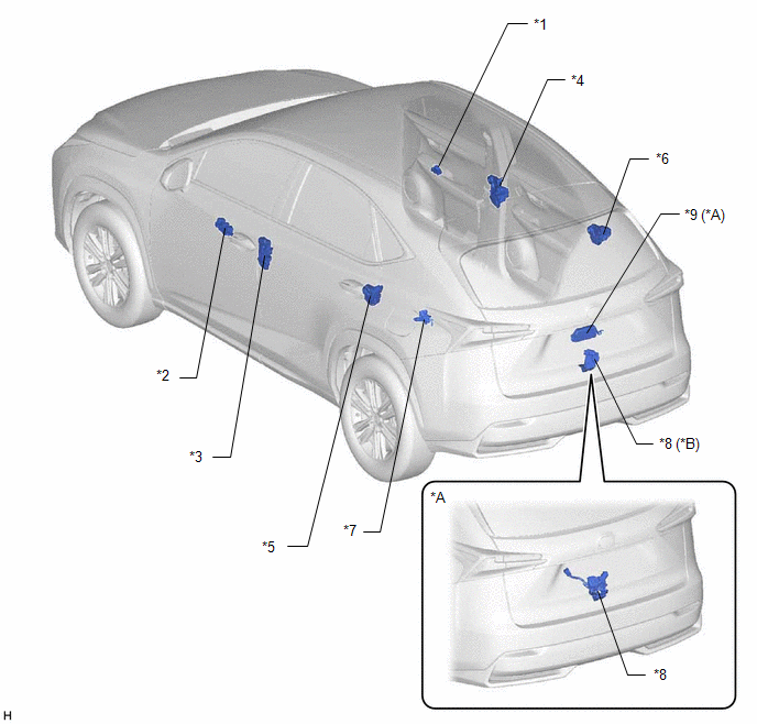
| *A | w/ Power Back Door System | *B | w/o Power Back Door System |
| *1 | DOOR CONTROL SWITCH | *2 | MULTIPLEX NETWORK MASTER SWITCH ASSEMBLY |
| *3 | FRONT DOOR LOCK ASSEMBLY LH | *4 | FRONT DOOR LOCK ASSEMBLY RH |
| *5 | REAR DOOR LOCK ASSEMBLY LH | *6 | REAR DOOR LOCK ASSEMBLY RH |
| *7 | FUEL LID WITH MOTOR LOCK ASSEMBLY | *8 | BACK DOOR LOCK ASSEMBLY |
| *9 | MULTIPLEX NETWORK DOOR ECU | - | - |
ILLUSTRATION
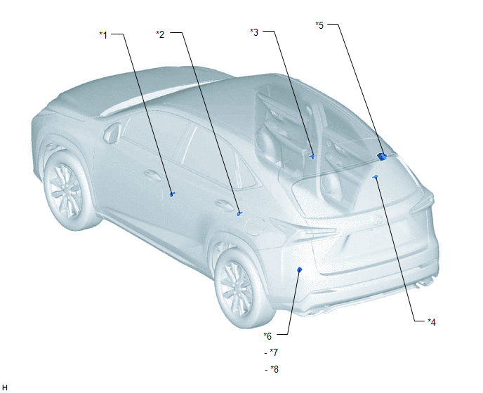
| *1 | FRONT DOOR COURTESY LIGHT SWITCH ASSEMBLY LH | *2 | FRONT DOOR COURTESY LIGHT SWITCH ASSEMBLY RH |
| *3 | REAR DOOR COURTESY LIGHT SWITCH ASSEMBLY LH | *4 | REAR DOOR COURTESY LIGHT SWITCH ASSEMBLY RH |
| *5 | ELECTRICAL KEY AND TMPS RECEIVER ASSEMBLY | *6 | FUSE BLOCK |
| *7 | ECU-B NO.3 FUSE | *8 | D/L NO.1 FUSE |
ILLUSTRATION
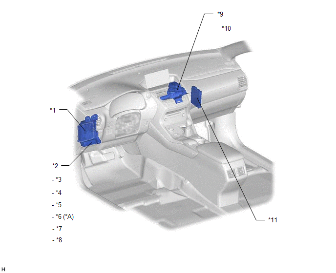
| *A | w/o Power Back Door System | - | - |
| *1 | MAIN BODY ECU (MULTIPLEX NETWORK BODY ECU) | *2 | INSTRUMENT PANEL JUNCTION BLOCK ASSEMBLY |
| *3 | D/L RELAY | *4 | D D/UL RELAY |
| *5 | D/UL RELAY | *6 | D/L BACK RELAY |
| *7 | ACC FUSE | *8 | ECU-IG NO.2 FUSE |
| *9 | NO. 3 RELAY BLOCK ASSEMBLY | *10 | FUEL LID OPENER RELAY |
| *11 | CERTIFICATION ECU (SMART KEY ECU ASSEMBLY) | - | - |
READ NEXT:
 System Diagram
SYSTEM DIAGRAM
Operation Check
OPERATION CHECK CHECK FUEL LID OPENER SYSTEM
*1:
*2:
*3: (a) Fuel lid unlock function: (1) With the fuel lid lock panel closed, unlock the doors using one of the following operations.
Problem Symptoms Table
PROBLEM SYMPTOMS TABLE NOTICE:
Recognition code registration is necessary when replacing the main body ECU (multiplex network body ECU).
If the main body ECU (multiplex network body ECU) is repla
SEE MORE:
Removal
REMOVAL CAUTION / NOTICE / HINT HINT:
Use the same procedure for the RH and LH sides.
The procedure described below is for the LH side.
PROCEDURE 1. REMOVE FRONT BUMPER ASSEMBLY Click here 2. REMOVE FOG LIGHT ASSEMBLY LH (a) Remove the 2 screws. (b) Detach the guide and remo
Headlight Cleaner Motor and Relay Circuit
DESCRIPTION The headlight ECU sub-assembly RH controls the headlight cleaner motor and pump assembly. WIRING DIAGRAM CAUTION / NOTICE / HINT NOTICE:
First check that the front washer operates normally.
Inspect the fuses for circuits related to this system before performing the following inspec
