Lexus NX: Automatic High Beam Main Switch
Inspection
INSPECTION
PROCEDURE
1. INSPECT COMBINATION SWITCH ASSEMBLY (AUTOMATIC HIGH BEAM MAIN SWITCH)
(a) Remove the combination switch assembly.
Click here .gif)
(b) Inspect the automatic high beam main switch.
| (1) Measure the resistance according to the value(s) in the table below. Standard Resistance:
If the result is not as specified, replace the combination switch assembly. |
|
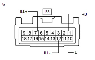
(c) Check the illumination.
(1) Apply auxiliary battery voltage to the connector and check the illumination conditions.
OK:
| Measurement Condition | Specified Condition |
|---|---|
| Auxiliary battery positive (+) → I33-7 (ILL+) Auxiliary battery negative (-) → I33-12 (ILL-) | Illuminates |
If the result is not as specified, replace the combination switch assembly.
READ NEXT:
 Precaution
PRECAUTION HANDLING PRECAUTIONS FOR FORWARD RECOGNITION CAMERA (a) The automatic high beam system uses the forward recognition camera. For precautions related to the forward recognition camera, refer
Parts Location
PARTS LOCATION ILLUSTRATION *1 FORWARD RECOGNITION CAMERA *2 BRAKE BOOSTER WITH MASTER CYLINDER ASSEMBLY (SKID CONTROL ECU) *3 HEADLIGHT ASSEMBLY LH *4 HEADLIGHT ASSEMBLY RH *5
SEE MORE:
Open in Pressure Sensor Circuit / Abnormal Refrigerant Pressure (B1423)
DESCRIPTION This DTC is stored if refrigerant pressure on the high pressure side is extremely low (176 kPa (1.8 kgf/cm2, 26 psi) or less) or extremely high (3025 kPa (30.8 kgf/cm2, 439 psi) or more). The air conditioning tube and accessory assembly (air conditioner pressure sensor), which is install
Vehicle Specifications have not been Stored (B2451)
DESCRIPTION This DTC is output if the vehicle variation information is not written to the headlight ECU sub-assembly LH. The headlight ECU sub-assembly LH outputs DTC B2451. DTC No. Detection Item DTC Detection Condition Trouble Area B2451 Vehicle Specifications have not been Stored
