Lexus NX: Parts Location
Lexus NX Service Manual / Vehicle Exterior / Lighting (ext) / Automatic High Beam System / Parts Location
PARTS LOCATION
ILLUSTRATION
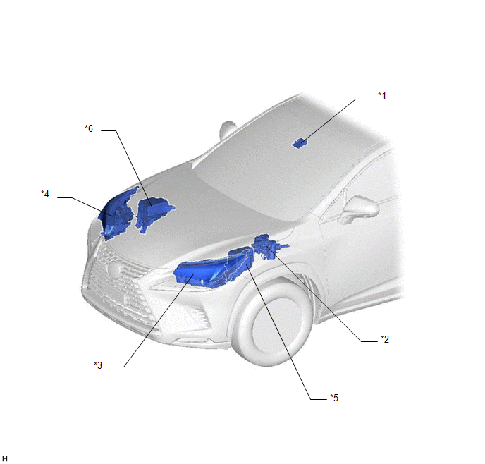
| *1 | FORWARD RECOGNITION CAMERA | *2 | BRAKE BOOSTER WITH MASTER CYLINDER ASSEMBLY (SKID CONTROL ECU) |
| *3 | HEADLIGHT ASSEMBLY LH | *4 | HEADLIGHT ASSEMBLY RH |
| *5 | ENGINE ROOM RELAY BLOCK - H-LP LH/DIMMER(HI) RELAY (for Single Beam Headlight) | *6 | NO. 2 ENGINE ROOM RELAY BLOCK - H-LP RH RELAY (for Triple Beam Headlight) |
ILLUSTRATION
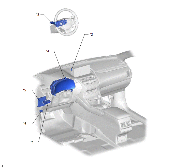
| *1 | COMBINATION SWITCH ASSEMBLY (AUTOMATIC HIGH BEAM MAIN SWITCH) | *2 | AUTOMATIC LIGHT CONTROL SENSOR |
| *3 | HEADLIGHT DIMMER SWITCH ASSEMBLY | *4 | COMBINATION METER ASSEMBLY |
| *5 | MAIN BODY ECU (MULTIPLEX NETWORK BODY ECU) | *6 | DLC3 |
READ NEXT:
 System Diagram
SYSTEM DIAGRAM
System Description
SYSTEM DESCRIPTION AUTOMATIC HIGH BEAM SYSTEM (a) General The automatic high beam system enhances the illumination of the area in front of the vehicle to improve visibility for the driver. It works by
How To Proceed With Troubleshooting
CAUTION / NOTICE / HINT HINT:
Use the following procedure to troubleshoot the automatic high beam system.
*: Use the Techstream.
PROCEDURE 1. VEHICLE BROUGHT TO WORKSHOP
NEXT
SEE MORE:
Sliding Roof ECU Communication Stop (B1273)
DESCRIPTION This DTC is stored when LIN communication between the sliding roof drive gear sub-assembly and main body ECU (multiplex network body ECU) stops for 10 seconds or more. DTC No. Detection Item DTC Detection Condition Trouble Area B1273 Sliding Roof ECU Communication Stop N
Removal
REMOVAL CAUTION / NOTICE / HINT HINT:
Use the same procedure for the RH and LH sides.
The following procedure is for the LH side.
NOTICE:
When the brake pedal is first depressed after replacing the brake pads or pushing back the disc brake piston, DTC C1214 may be output. As there is no m
© 2016-2026 Copyright www.lexunx.com
