Lexus NX: Back Camera Disconnected (C1622)
DESCRIPTION
This DTC is stored if the radio receiver assembly judges that the signals or signal lines between the television camera assembly and the multi-display assembly are not normal as a result of its self check.
| DTC No. | Detection Item | DTC Detection Condition | Trouble Area |
|---|---|---|---|
| C1622 | Back Camera Disconnected | Open or short in the television camera assembly signal circuit |
|
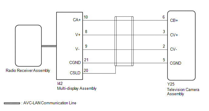
WIRING DIAGRAM
CAUTION / NOTICE / HINT
NOTICE:
-
If the cable was disconnected from and reconnected to the negative (-) auxiliary battery terminal, the estimated course lines may not be displayed on the image of the area behind the vehicle. In this case, perform "Correct the Steering Angle Neutral Point".
Click here
.gif)
-
Depending on the parts that are replaced or operations that are performed during vehicle inspection or maintenance, calibration of other systems as well as the parking assist monitor system may be needed.
Click here
-
When replacing the radio receiver assembly, always replace it with a new one.
If a radio receiver assembly which was installed to another vehicle is used, the following may occur:
- A communication malfunction DTC may be stored.
- The radio receiver assembly may not operate normally.
HINT:
Depending on the parts that are replaced during vehicle inspection or maintenance, performing initialization, registration or calibration may be needed. Refer to Precaution for Audio and Visual System.
Click here
PROCEDURE
| 1. | CHECK HARNESS AND CONNECTOR (TELEVISION CAMERA ASSEMBLY - MULTI-DISPLAY ASSEMBLY) |
(a) Disconnect the Y25 television camera assembly connector.
(b) Disconnect the I42 multi-display assembly connector.
(c) Measure the resistance according to the value(s) in the table below.
Standard Resistance:
| Tester Connection | Condition | Specified Condition |
|---|---|---|
| Y25-6 (CB+) - I42-10 (CA+) | Always | Below 1 Ω |
| Y25-3 (CV+) - I42-8 (V+) | Always | Below 1 Ω |
| Y25-2 (CV-) - I42-9 (V-) | Always | Below 1 Ω |
| Y25-5 (CGND) - I42-21 (CGND) | Always | Below 1 Ω |
| Y25-6 (CB+) or I42-10 (CA+) - Body ground | Always | 10 kΩ or higher |
| Y25-3 (CV+) or I42-8 (V+) - Body ground | Always | 10 kΩ or higher |
| Y25-2 (CV-) or I42-9 (V-) - Body ground | Always | 10 kΩ or higher |
| Y25-5 (CGND) or I42-21 (CGND) - Body ground | Always | 10 kΩ or higher |
| NG | .gif) | REPAIR OR REPLACE HARNESS OR CONNECTOR |
|
.gif)
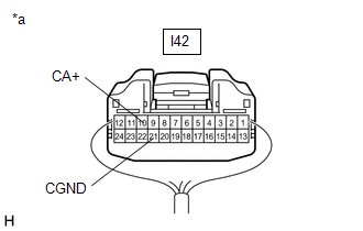
| 2. | CHECK MULTI-DISPLAY ASSEMBLY (CA+, CGND) |
| (a) Remove the multi-display assembly with the connector still connected. Click here |
|
(b) Measure the voltage according to the value(s) in the table below.
Standard Voltage:
| Tester Connection | Switch Condition | Specified Condition |
|---|---|---|
| I42-10 (CA+) - I42-21 (CGND) | Power switch on (ACC) | 5.5 to 7.05 V |
(c) Measure the resistance according to the value(s) in the table below.
Standard Resistance:
| Tester Connection | Condition | Specified Condition |
|---|---|---|
| I42-21 (CGND) - Body ground | Always | Below 1 Ω |
| NG | | REPLACE MULTI-DISPLAY ASSEMBLY |
|
| 3. | CHECK TELEVISION CAMERA ASSEMBLY |
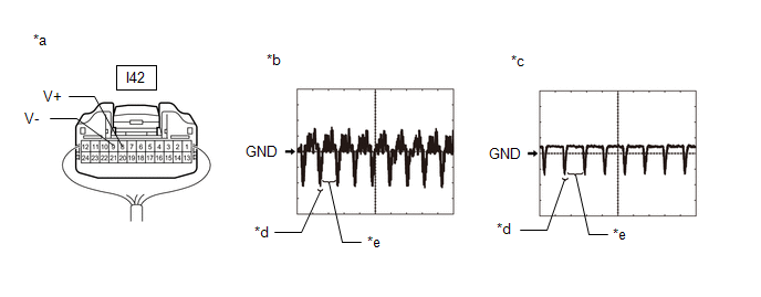
| *a | Component with harness connected | *b | Waveform 1 |
| *c | Waveform 2 | *d | Synchronization Signal |
| *e | Video Waveform | - | - |
(a) Remove the multi-display assembly with the connector still connected.
Click here
(b) Check the waveform of the television camera assembly using an oscilloscope.
| Item | Content |
| Measurement terminal | I42-8 (V+) - I42-9 (V-) |
| Measurement setting | 200 mV/DIV., 50 μsec./DIV. |
| Condition | Waveform 1: Power switch on (READY), shift position in R, camera lens is not covered, displaying an image. Waveform 2: Power switch on (READY), shift position in R, camera lens is covered, blacking out the screen. |
HINT:
- The video waveform changes according to the image sent by the television camera assembly.
- The video waveform is constantly output when the power switch is on (ACC).
OK:
Waveform is as shown in the illustration.
| NG | | REPLACE TELEVISION CAMERA ASSEMBLY |
|
| 4. | CHECK MULTI-DISPLAY ASSEMBLY |
(a) Replace the multi-display assembly with a new or known good one.
Click here
(b) Clear the DTCs.
Click here
(c) Check for DTCs and check that no DTCs are output.
Click here
| Result | Proceed to |
|---|---|
| DTC C1622 is not output | A |
| DTC C1622 is output | B |
| A | | END |
| B | | REPLACE RADIO RECEIVER ASSEMBLY |
READ NEXT:
 Sending Malfunction (Navigation to APGS) (U0073,U0100,U0129,U0140,U0155,U0164,U0198,U023B,U0265,U0293,U1110)
DESCRIPTION These DTCs are stored when a malfunction occurs in the CAN communication circuit. DTC No. Detection Item DTC Detection Condition Trouble Area U0073 Sending Malfunction (Navi
Satellite Radio Broadcast cannot be Received
WIRING DIAGRAM CAUTION / NOTICE / HINT NOTICE:
Some satellite radio broadcasts require payment. A contract must be made between a satellite radio company and the user. If the contract expires, it
Satellite Radio Broadcast cannot be Selected or After Selecting Broadcast, Broadcast cannot be Added into Memory
CAUTION / NOTICE / HINT NOTICE:
Some satellite radio broadcasts require payment. A contract must be made between a satellite radio company and the user. If the contract expires, it will not be poss
SEE MORE:
Removal
REMOVAL PROCEDURE 1. PRECAUTION CAUTION: The hybrid system has high-voltage circuits. Accidents, such as electric shock, or electric leaks may result if the hybrid system is not operated in a correct manner. Make sure to follow the correct procedure. Click here NOTICE: After turning the power swit
Components
COMPONENTS ILLUSTRATION *1 FRONT FENDER FRONT SPLASH SHIELD RH *2 FRONT FENDER LINER RH *3 FRONT FENDER MOULDING SUB-ASSEMBLY RH *4 LEVEL WARNING SWITCH ASSEMBLY *5 NO. 1 MOULDING TAPE *6 NO. 2 MOULDING TAPE *7 GROMMET - - ● Non-reusable part - -
