Lexus NX: Seat Heater for Rear Left Seat does not Operate
DESCRIPTION
When the refreshing seat switch is operated, the air conditioning amplifier assembly receives the signal via the LIN communication line, and operates the seat heater for the corresponding rear seat.
WIRING DIAGRAM
.png)
.png)
CAUTION / NOTICE / HINT
NOTICE:
-
If the auxiliary battery voltage is low, the seat heater system may not operate. When "High Power Consumption / Partial Limit On AC/Heater Operation" is displayed on the multi-information display in the combination meter assembly, inspect the auxiliary battery, referring to On-vehicle Inspection for the charging system.
HINT:
If the auxiliary battery voltage is low, "Operation Limitation Control History Count (Level 1)" and "Operation Limitation Control History Count (Level 2) is counted.
Click here
.gif)
Click here
-
If the auxiliary battery voltage is low, the seat heater system may not operate. Refer to Data List for the power steering system.
-
for Manual Tilt and Manual Telescopic Steering Column:
-
for Power Tilt and Power Telescopic Steering Column:
-
for Manual Tilt and Manual Telescopic Steering Column:
- Inspect the fuses for circuits related to this system before performing the following procedure.
-
When the auxiliary battery is disconnected or the air conditioning amplifier assembly is replaced, be sure to perform servo motor initialization.
Click here
PROCEDURE
| 1. | CLEAR DTC |
(a) Clear the DTCs.
Click here
|
.gif)
| 2. | CHECK FOR DTC |
(a) Check for DTCs.
Click here
OK:
DTC B14C3 is not output.
| NG | .gif) | GO TO DTC B14C3 |
|
| 3. | CHECK HARNESS AND CONNECTOR (SEPARATE TYPE REAR SEATBACK COVER LH - BATTERY AND BODY GROUND) |
| (a) Disconnect the separate type rear seatback cover LH connector. |
|
(b) Measure the resistance according to the value(s) in the table below.
Standard Resistance:
| Tester Connection | Condition | Specified Condition |
|---|---|---|
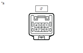
| i7-4 - Body ground | Always | Below 1 Ω |
(c) Measure the voltage according to the value(s) in the table below.
Standard Voltage:
| Tester Connection | Condition | Specified Condition |
|---|---|---|
| i7-1 - Body ground | Power switch on (IG) | 11 to 14 V |
| i7-1 - Body ground | Power switch off | Below 1 V |
| NG | | REPAIR OR REPLACE HARNESS OR CONNECTOR |
|
| 4. | INSPECT SEPARATE TYPE REAR SEATBACK COVER LH |
(a) Remove the separate type rear seatback cover LH.
-
for Manual Seat:
-
for Power Seat:
(b) Inspect the separate type rear seatback cover LH.
-
for Manual Seat:
-
for Power Seat:
| NG | | REPLACE SEPARATE TYPE SEATBACK COVER RH |
|
| 5. | CHECK HARNESS AND CONNECTOR (SEPARATE TYPE REAR SEATBACK COVER LH - AIR CONDITIONING AMPLIFIER ASSEMBLY) |
(a) Disconnect the i7 separate type rear seatback cover LH connector.
(b) Disconnect the I50 air conditioning amplifier assembly connector.
(c) Measure the resistance according to the value(s) in the table below.
Standard Resistance:
| Tester Connection | Condition | Specified Condition |
|---|---|---|
| i7-5 - I50-36 (SHDE) | Always | Below 1 Ω |
| i7-5 or I50-36 (SHDE) - Body ground | Always | 10 kΩ or higher |
| NG | | REPAIR OR REPLACE HARNESS OR CONNECTOR |
|
| 6. | CHECK HARNESS AND CONNECTOR (BENCH TYPE REAR SEAT CUSHION COVER - SEPARATE TYPE REAR SEATBACK COVER LH AND BODY GROUND) |
(a) Disconnect the i6 bench type seat cushion cover connector.
(b) Disconnect the i7 separate type rear seatback cover LH connector.
(c) Measure the resistance according to the value(s) in the table below.
Standard Resistance:
| Tester Connection | Condition | Specified Condition |
|---|---|---|
| i6-5 - i7-3 | Always | Below 1 Ω |
| i6-4 - i7-2 | Always | Below 1 Ω |
| i6-1 - Body ground | Always | Below 1 Ω |
| i6-5 or i7-3 - Body ground | Always | 10 kΩ or higher |
| i6-4 or i7-2 - Body ground | Always | 10 kΩ or higher |
| NG | | REPAIR OR REPLACE HARNESS OR CONNECTOR |
|
| 7. | INSPECT BENCH TYPE REAR SEAT CUSHION COVER |
(a) Remove the bench type rear seat cushion cover.
-
for Manual Seat:
-
for Power Seat:
(b) Inspect the bench type rear seat cushion cover.
-
for Manual Seat:
-
for Power Seat:
| NG | | REPLACE BENCH TYPE REAR SEAT CUSHION COVER |
|
| 8. | CHECK SEAT HEATER CONTROL SUB-ASSEMBLY LH |
(a) Temporarily replace the seat heater control sub-assembly LH with a new or known good one.
Click here
OK:
The seat heater operates normally.
| OK | | END (SEAT HEATER CONTROL SUB-ASSEMBLY LH WAS DEFECTIVE) |
| NG | | REPLACE AIR CONDITIONING AMPLIFIER ASSEMBLY |
READ NEXT:
 Components
COMPONENTS ILLUSTRATION *1 FRONT DOOR INSIDE HANDLE BEZEL PLUG LH *2 FRONT DOOR TRIM BOARD SUB-ASSEMBLY LH *3 FRONT DOOR TRIM COVER LH *4 FRONT SEAT SLIDE SWITCH BEZEL *5 POW
Removal
REMOVAL PROCEDURE 1. REMOVE FRONT DOOR TRIM COVER LH Click here 2. REMOVE FRONT DOOR INSIDE HANDLE BEZEL PLUG LH Click here 3. REMOVE POWER WINDOW REGULATOR MASTER SWITCH ASSEMBLY WITH FRONT DOO
SEE MORE:
Installation
INSTALLATION PROCEDURE 1. INSTALL MOBILEPHONE BATTERY CAUTION:
Do not reuse dropped or damaged parts.
Wear gloves when contacting parts that have been dropped from a height of 1 m or higher.
There may be an internal short or the temperature may increase to 100°C or higher due to the shock fr
PIG Power Supply Voltage (C1552,C1554)
DESCRIPTION When a problem occurs in the power steering system, the power source relay circuit is shut off to stop the power assist. DTC No. Detection Item DTC Detection Condition Trouble Area Warning Indicate Return-to-normal Condition Note C1552 PIG Power Supply Voltage PIG
