Lexus NX: Back Door Support
Components
COMPONENTS
ILLUSTRATION
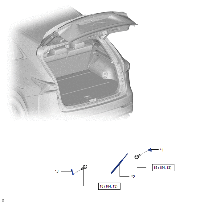
| *1 | BACK DOOR LOWER DAMPER STAY BRACKET LH | *2 | BACK DOOR STAY ASSEMBLY LH |
| *3 | BACK DOOR UPPER DAMPER STAY BRACKET LH | - | - |
.png) | N*m (kgf*cm, ft.*lbf): Specified torque | ★ | Precoated part |
Removal
REMOVAL
CAUTION / NOTICE / HINT
HINT:
- Use the same procedure for the RH and LH sides.
- The procedure listed below is for the LH side.
PROCEDURE
1. REMOVE BACK DOOR STAY ASSEMBLY LH
NOTICE:
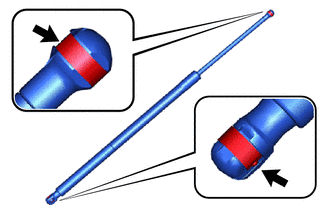
- Avoid touching the piston rod as much as possible to prevent foreign matter from attaching to it. Be sure to hold the cylinder while servicing.
- Do not wear cotton gloves or other similar materials when handling the piston rod. Fibers may attach to the rod and result in gas leaks.
- Do not push sideways on the cylinder because the rod may bend.
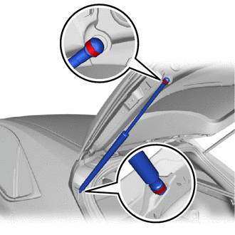
| (a) Using a thin-bladed screwdriver with its tip wrapped in protective tape, remove the 2 stop rings along their grooves. HINT: Tape the thin-bladed screwdriver tip before use. |
|
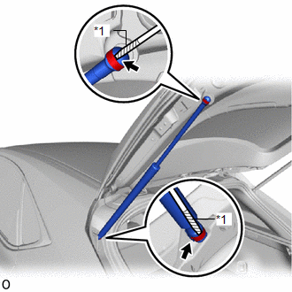
(b) Detach the 2 ball joints and remove the back door stay assembly LH.
NOTICE:
Remove the back door stay assembly LH while supporting the back door by hand.
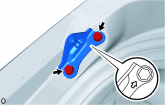
2. REMOVE BACK DOOR LOWER DAMPER STAY BRACKET LH
| (a) Remove the 2 bolts and back door lower damper stay bracket LH. |
|

3. REMOVE BACK DOOR UPPER DAMPER STAY BRACKET LH
| (a) Remove the 2 bolts and back door upper damper stay bracket LH. |
|
Installation
INSTALLATION
CAUTION / NOTICE / HINT
HINT:
- Use the same procedure for the RH and LH sides.
- The procedure listed below is for the LH side.
PROCEDURE
1. INSTALL BACK DOOR UPPER DAMPER STAY BRACKET LH
(a) When replacing the back door stay bolt with a new one:
(1) Clean the threaded portion on the vehicle body with non-residue solvent.
(b) When reusing the back door stay bolt:
(1) Clean the threaded portion on the vehicle body with non-residue solvent.
(2) Apply adhesive to the threads of the 2 bolts.
Adhesive:
Toyota Genuine Adhesive 1324, Three Bond 1324 or equivalent
| (c) Temporarily install the back door damper stay upper bracket LH. |
|

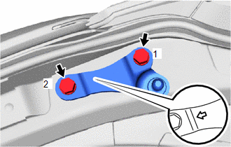
(d) Tighten the 2 bolts to install the back door damper stay upper bracket LH.
HINT:
Tighten the 2 bolts in the order shown in the illustration.
Torque:
18 N·m {184 kgf·cm, 13 ft·lbf}
2. INSTALL BACK DOOR LOWER DAMPER STAY BRACKET LH
(a) When replacing the back door stay bolt with a new one:
(1) Clean the threaded portion on the vehicle body with non-residue solvent.
(b) When reusing the back door stay bolt:
(1) Clean the threaded portion on the vehicle body with non-residue solvent.
(2) Apply adhesive to the threads of the 2 bolts.
Adhesive:
Toyota Genuine Adhesive 1324, Three Bond 1324 or equivalent
| (c) Temporarily install the back door lower damper stay bracket LH. |
|
(d) Tighten the 2 bolts to install the back door lower damper stay bracket LH.
HINT:
Tighten the 2 bolts in the order shown in the illustration.
Torque:
18 N·m {184 kgf·cm, 13 ft·lbf}
3. INSTALL BACK DOOR STAY ASSEMBLY LH
(a) When reusing the back door stay assembly LH:
| (1) Install the back door stay assembly LH with the 2 stop rings. |
|
| (b) Install the back door stay assembly LH. NOTICE:
|
|
Disposal
DISPOSAL
CAUTION / NOTICE / HINT
PROCEDURE
1. DISPOSE OF BACK DOOR STAY ASSEMBLY LH
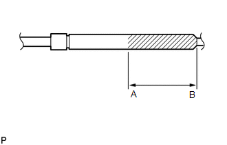
(a) Horizontally hold the hood support in a vise with the piston rod pulled out.
| (b) Wear safety glasses. Gradually cut a part between A and B shown in the illustration using a metal saw to release the gas.
NOTICE: Although the gas inside the hood support is colorless, odorless and harmless, there is a possibility that metal debris could scatter. Therefore, cover it with a piece of cloth or other material. |
|
READ NEXT:
 Back Door Weatherstrip
ComponentsCOMPONENTS ILLUSTRATION *1 BACK DOOR WEATHERSTRIP - - ● Non-reusable part - - RemovalREMOVAL PROCEDURE 1. REMOVE BACK DOOR WEATHERSTRIP (a) Remove the back door
Components
COMPONENTS ILLUSTRATION *1 DECK FLOOR BOX LH *2 NO. 3 DECK BOARD SUB-ASSEMBLY *3 REAR DECK FLOOR BOX *4 NEGATIVE AUXILIARY BATTERY TERMINAL N*m (kgf*cm, ft.*lbf): Specified
SEE MORE:
Problem Symptoms Table
PROBLEM SYMPTOMS TABLE NOTICE: When replacing the combination meter assembly, always replace it with a new one. If a combination meter assembly which was installed to another vehicle is used, the information stored in it will not match the information from the vehicle and a DTC may be stored. HINT:
Stereo Component Amplifier Disconnected (B15D3)
DESCRIPTION The radio receiver assembly and stereo component amplifier assembly are connected by the MOST communication line. This DTC is stored when a MOST communication error occurs between the radio receiver assembly and stereo component amplifier assembly. DTC No. Detection Item DTC Detec
