Lexus NX: Back-up Power Source Circuit
DESCRIPTION
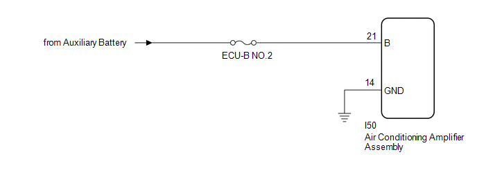
The back-up power source circuit for the air conditioning amplifier assembly is shown below. Power is supplied even when the power switch is off. The power is used for diagnostic trouble code memory, etc.
WIRING DIAGRAM
CAUTION / NOTICE / HINT
NOTICE:
Inspect the fuses for circuits related to this system before performing the following procedure.
PROCEDURE
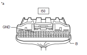
| 1. | CHECK HARNESS AND CONNECTOR (AIR CONDITIONING AMPLIFIER ASSEMBLY - BATTERY AND BODY GROUND) |
| (a) Disconnect the air conditioning amplifier assembly connectors. |
|
(b) Measure the voltage according to the value(s) in the table below.
Standard Voltage:
| Tester Connection | Switch Condition | Specified Condition |
|---|---|---|
| I50-21 (B) - Body ground | Power switch off | 11 to 14 V |
(c) Measure the resistance according to the value(s) in the table below.
Standard Resistance:
| Tester Connection | Condition | Specified Condition |
|---|---|---|
| I50-14 (GND) - Body ground | Always | Below 1 Ω |
| OK | .gif) | PROCEED TO NEXT SUSPECTED AREA SHOWN IN PROBLEM SYMPTOMS TABLE |
.gif)
| NG | | REPAIR OR REPLACE HARNESS OR CONNECTOR |
READ NEXT:
 Removal
REMOVAL PROCEDURE 1. RECOVER REFRIGERANT FROM REFRIGERATION SYSTEM Click here 2. DRAIN ENGINE COOLANT Click here 3. DISCONNECT AIR CONDITIONER TUBE AND ACCESSORY ASSEMBLY (a) Remove the bolt an
Disassembly
DISASSEMBLY PROCEDURE 1. REMOVE AIR CONDITIONING RADIATOR ASSEMBLY (a) Disconnect the No. 1 blower damper servo sub-assembly connector. (b) Detach the 3 clamps and remove the air condit
SEE MORE:
Dtc Check / Clear
DTC CHECK / CLEAR DTC CHECK USING TECHSTREAM (a) Connect the Techstream to the DLC3. (b) Turn the power switch on (IG). (c) Turn the Techstream on. (d) Enter the following menus: Body Electrical / Air Conditioner / Trouble Codes. (e) Check for DTCs. Click here Body Electrical > Air Conditioner &
Installation
INSTALLATION PROCEDURE 1. INSTALL VEHICLE APPROACHING SPEAKER CONTROLLER (a) Connect the connector. (b) Attach the hook to install the vehicle approaching speaker controller. NOTICE:
When installing the vehicle approaching speaker controller, take care not to damage it.
Do not reuse a vehicle a
