Lexus NX: Removal
REMOVAL
PROCEDURE
1. RECOVER REFRIGERANT FROM REFRIGERATION SYSTEM
Click here .gif)
2. DRAIN ENGINE COOLANT
Click here
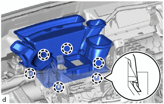
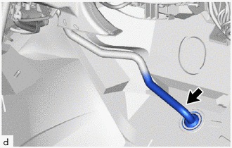
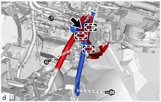
3. DISCONNECT AIR CONDITIONER TUBE AND ACCESSORY ASSEMBLY
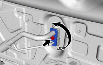
| (a) Remove the bolt and rotate the hook connector as shown in the illustration. |
|
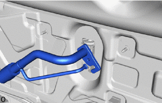
| (b) Disconnect the air conditioner tube and accessory assembly. |
|
(c) Remove the 2 O-rings from the air conditioner tube and accessory assembly.
NOTICE:
Seal the openings of the disconnected parts using vinyl tape to prevent the entry of moisture and foreign matter.
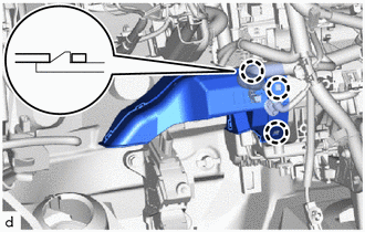
4. DISCONNECT HEATER WATER OUTLET HOSE A
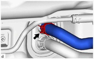
| (a) Using pliers, grip the claws of the clip and slide the clip to disconnect the heater water outlet hose A. NOTICE:
|
|
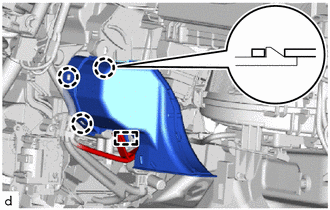
5. DISCONNECT WATER HOSE SUB-ASSEMBLY B
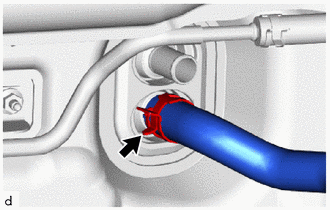
| (a) Using pliers, grip the claws of the clip and slide the clip to disconnect the water hose sub-assembly B. NOTICE:
|
|
6. REMOVE LOWER INSTRUMENT PANEL
Click here
7. REMOVE STEERING COLUMN ASSEMBLY
(a) for Manual Tilt and Manual Telescopic Steering Column:
Click here
(b) for Power Tilt and Power Telescopic Steering Column:
Click here
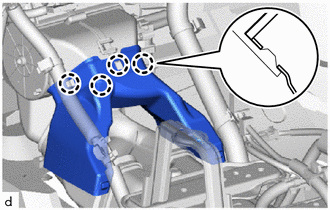
8. REMOVE LOWER DEFROSTER NOZZLE ASSEMBLY
| (a) Detach the 6 claws and remove the lower defroster nozzle assembly. |
|
9. REMOVE FRONT SEAT ASSEMBLY LH
Click here
10. REMOVE FRONT SEAT ASSEMBLY RH
HINT:
Use the same procedure described for the LH side.
11. REMOVE REAR NO. 3 AIR DUCT
| (a) Using a clip remover, remove the 2 clips. |
|
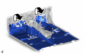
(b) Fold back the front floor carpet assembly far enough so that the rear No. 3 air duct and rear No. 2 air duct can be removed.
| (c) Using a clip remover, remove the clip. |
|
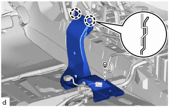
(d) Detach the 2 claws and remove the rear No. 3 air duct.
12. REMOVE REAR NO. 2 AIR DUCT
| (a) Using a clip remover, remove the clip. |
|
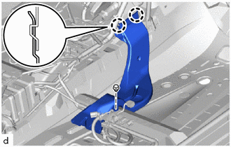
(b) Detach the 2 claws and remove the rear No. 2 air duct.
13. DISCONNECT DRAIN COOLER HOSE
| (a) Disconnect the drain cooler hose. |
|
14. REMOVE NO. 1 AIR DUCT
| (a) Detach the 3 claws and remove the No. 1 air duct. NOTICE:
|
|
15. REMOVE NO. 2 AIR DUCT
| (a) Detach the clamp. |
|
(b) Detach the 3 claws and remove the No. 2 air duct.
NOTICE:
- When removing, do not crack or deform the upper heater case of the air conditioning radiator assembly.
- If the No. 2 air duct is reused, it may fall off or abnormal noise may occur. Therefore, make sure to replace with a new one.
16. REMOVE NO. 1 INSTRUMENT PANEL BRACE SUB-ASSEMBLY
| (a) Detach the 4 clamps and disconnect the wire harness. |
|
(b) Remove the bolt, screw, 2 nuts and No. 1 instrument panel brace sub-assembly.
17. REMOVE NO. 2 INSTRUMENT PANEL BRACE SUB-ASSEMBLY
| (a) Detach the 3 clamps and disconnect the wire harness. |
|
(b) Remove the bolt and disconnect the ground wire.
(c) Remove the bolt, screw, nut and No. 2 instrument panel brace sub-assembly.
18. REMOVE REAR NO. 1 AIR DUCT
| (a) Detach the 4 claws and remove the rear No. 1 air duct. |
|
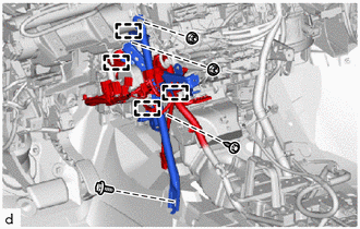
19. DISCONNECT INSTRUMENT PANEL WIRE
(a) Remove the 4 bolts and disconnect the 4 ground wires.
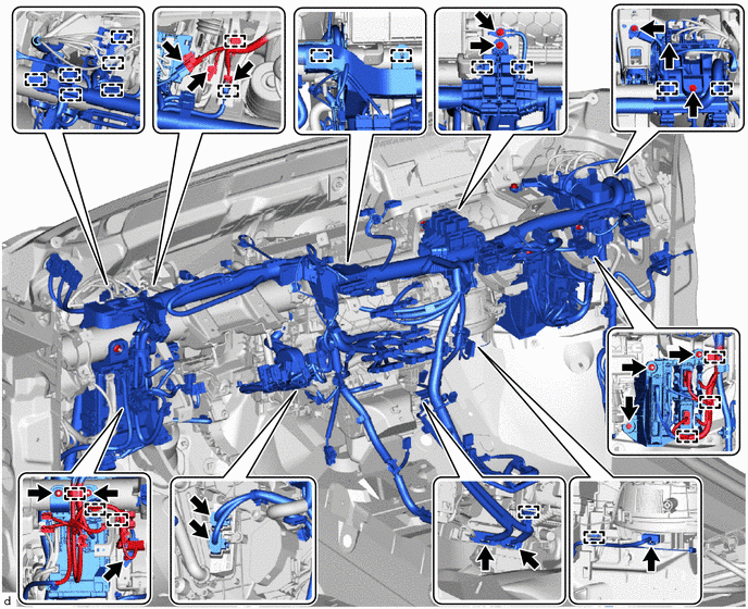
(b) Disconnect each connectors and detach each clamps.
(c) Remove the 3 nuts and disconnect the instrument panel junction block assembly.
(d) Remove the bolt and 2 nuts and disconnect the ECU integration box RH.
(e) Remove the bolts and disconnect the instrument panel wire.
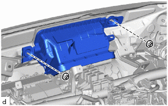
20. REMOVE AIR DUCT ASSEMBLY
| (a) Remove the 2 nuts and air duct assembly. |
|
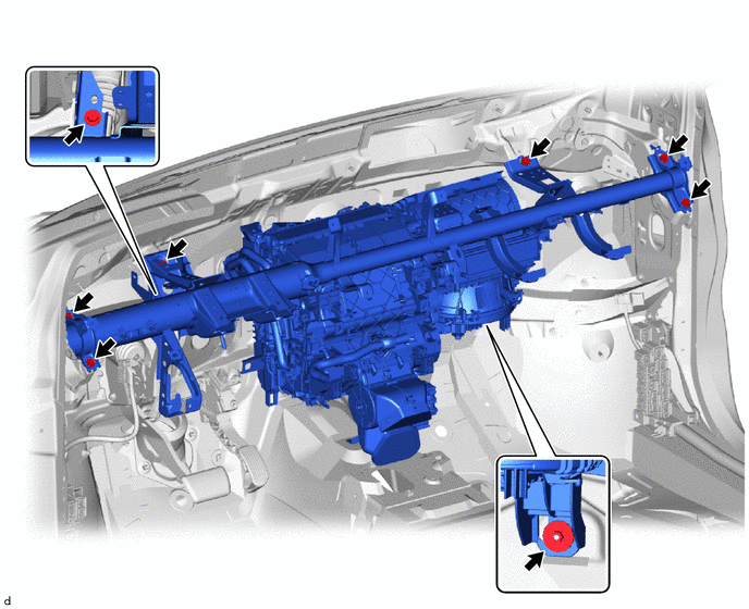
21. REMOVE INSTRUMENT PANEL REINFORCEMENT ASSEMBLY WITH AIR CONDITIONING UNIT ASSEMBLY
(a) Remove the 7 bolts, nut and the instrument panel reinforcement assembly with air conditioning unit assembly.
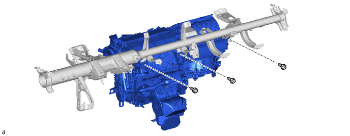
22. REMOVE AIR CONDITIONING UNIT ASSEMBLY
(a) Remove the 3 bolts and air conditioning unit assembly.
READ NEXT:
 Disassembly
DISASSEMBLY PROCEDURE 1. REMOVE AIR CONDITIONING RADIATOR ASSEMBLY (a) Disconnect the No. 1 blower damper servo sub-assembly connector. (b) Detach the 3 clamps and remove the air condit
Reassembly
REASSEMBLY PROCEDURE 1. INSTALL NO. 1 COOLER THERMISTOR Click here 2. INSTALL NO. 1 COOLER EVAPORATOR SUB-ASSEMBLY (a) Sufficiently apply compressor oil to 2 new O-rings and the fitting surface of t
Installation
INSTALLATION CAUTION / NOTICE / HINT HINT:
Use the same procedure for the RH and LH sides.
The procedure listed below is for the LH side.
A bolt without a torque specification is shown in the s
SEE MORE:
Power Back Door cannot be Operated Using Kick Sensor
DESCRIPTION The kick door control sensor receives vehicle speed, IG and ACC signals from the main body ECU (multiplex network body ECU) via LIN communication and uses the information to stop sensor oscillation. When the kick door control sensor detects a kick operation, it sends a operation signal t
Security Horn Assembly
ComponentsCOMPONENTS ILLUSTRATION *1 SECURITY HORN ASSEMBLY - - N*m (kgf*cm, ft.*lbf): Specified torque - - RemovalREMOVAL PROCEDURE 1. REMOVE SECURITY HORN ASSEMBLY (a) Remove the bolt and detach the guide. (b) Disconnect the connector and remove the securit
