- DTC judgment completed
- System normal
Lexus NX: Camshaft Position "A" - Timing Over-Advanced or System Performance (Bank 1) (P0011,P0012)
Lexus NX Service Manual / Engine & Hybrid System / 2ar-fxe (engine Control) / Sfi System / Camshaft Position "A" - Timing Over-Advanced or System Performance (Bank 1) (P0011,P0012)
DESCRIPTION
Refer to DTC P0010.
Click here .gif)
| DTC No. | Detection Item | DTC Detection Condition | Trouble Area | MIL | Memory |
|---|---|---|---|---|---|
| P0011 | Camshaft Position "A" - Timing Over-Advanced or System Performance (Bank 1) | Intake valve timing is stuck at a certain value when in the advance range (1 trip detection logic). |
| Comes on | DTC stored |
| P0012 | Camshaft Position "A" - Timing Over-Retarded (Bank 1) | Intake valve timing is stuck at a certain value when in the retard range (2 trip detection logic). |
| Comes on | DTC stored |
MONITOR DESCRIPTION
The ECM optimizes the intake valve timing using the Variable Valve Timing (VVT) system to control the intake camshaft. The VVT system includes the ECM, camshaft timing oil control valve assembly and VVT controller (camshaft timing gear assembly). The ECM sends a target duty-cycle control signal to the camshaft timing oil control valve assembly. This control signal regulates the oil pressure supplied to the VVT controller. The VVT controller can advance or retard the intake camshaft.
If the difference between the target and actual intake valve timing is large, and changes in the actual intake valve timing are small, the ECM interprets this as a VVT controller stuck malfunction and stores a DTC.
- Example:
-
A DTC is stored when the following conditions "A" and "B" are met:
- It takes 5 seconds or more to change the valve timing by 5°CA (Condition "A").
- After condition "A" is met, the camshaft timing oil control valve assembly is forcibly activated for 10 seconds (Condition "B").
DTC P0011 (Advanced Cam Timing) is subject to 1 trip detection logic.
DTC P0012 (Retarded Cam Timing) is subject to 2 trip detection logic.
These DTCs indicate that the VVT controller cannot operate properly due to a camshaft timing oil control valve assembly malfunction or the presence of foreign matter in the camshaft timing oil control valve assembly.
MONITOR STRATEGY
| Related DTCs | P0011: Advanced camshaft timing P0012: Retarded camshaft timing |
| Required Sensors/Components (Main) | Camshaft timing oil control valve assembly Camshaft timing gear assembly |
| Required Sensors/Components (Related) | Crankshaft position sensor Camshaft position sensor Engine coolant temperature sensor |
| Frequency of Operation | Continuous |
| Duration | Within 10 seconds |
| MIL Operation | Advanced camshaft timing: Immediate Retarded camshaft timing: 2 driving cycles |
| Sequence of Operation | None |
TYPICAL ENABLING CONDITIONS
| Monitor runs whenever the following DTCs are not stored | P0010 (Camshaft timing oil control valve) P0016 (VVT system - misalignment) P0102, P0103 (Mass air flow meter) P0107, P0108 (Manifold absolute pressure) P0115, P0117, P0118 (Engine coolant temperature sensor) P0125 (Insufficient coolant temperature for closed loop fuel control) P0335 (Crankshaft position sensor) P0340 (Camshaft position sensor) |
| Auxiliary battery voltage | 11 V or higher |
| Engine speed | 500 to 4000 rpm |
| Engine coolant temperature | 73 to 100°C (163 to 212°F) |
TYPICAL MALFUNCTION THRESHOLDS
P0011: Advanced Camshaft Timing| Both of the following conditions are met | - |
| Deviation of actual valve timing and target valve timing | More than 5°CA (Crankshaft Angle) for 5 seconds or more after the VVT hold duty ratio learned value reaches the upper or lower limit. |
| Valve timing | No change at advanced valve timing |
| Both of the following conditions are met | - |
| Deviation of actual valve timing and target valve timing | More than 5°CA (Crankshaft Angle) for 5 seconds or more after the VVT hold duty ratio learned value reaches the upper or lower limit. |
| Valve timing | No change at retarded valve timing |
If the difference between the target and actual camshaft timing is greater than the specified value, the ECM operates the VVT actuator (camshaft timing oil control valve assembly) for 10 seconds by applying and releasing oil pressure. Then, the ECM monitors the camshaft timing change for 10 seconds.
MONITOR RESULT
Refer to detailed information in Checking Monitor Status.
Click here
| Monitor ID | Test ID | Scaling | Unit | Description |
|---|---|---|---|---|
| $35 | $81 | Multiply by 0.01 | Second | Forced movement of cam timing control actuator time |
CONFIRMATION DRIVING PATTERN
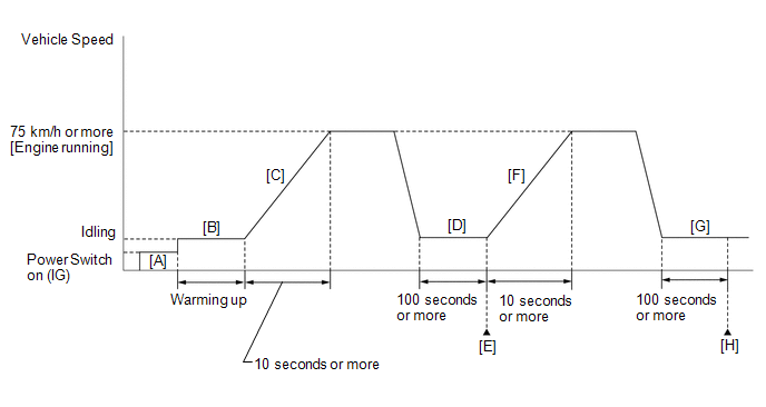
- Connect the Techstream to the DLC3.
- Turn the power switch on (IG) and turn the Techstream on.
-
Clear the DTCs (even if no DTCs are stored, perform the clear DTC procedure).
HINT:
-
P0011 is output:
Clear the DTC not using the Techstream.
-
P0012 is output:
Clear the DTC using the Techstream.
-
P0011 is output:
- Turn the power switch off and wait for at least 30 seconds.
- Turn the power switch on (IG) and turn the Techstream on [A].
-
Put the engine in inspection mode (maintenance mode).
Click here
- Start the engine and warm it up until the engine coolant temperature reaches 75°C (167°F) or higher [B].
-
With the engine running, accelerate the vehicle to 75 km/h (46 mph) or more by depressing the accelerator pedal for 10 seconds or more [C].
CAUTION:
When performing the confirmation driving pattern, obey all speed limits and traffic laws.
HINT:
If the engine stops, further depress the accelerator pedal to restart the engine.
-
Idle the engine for 100 seconds or more [D].
HINT:
-
P0011 is output:
With the shift lever in P.
-
P0012 is output:
With the shift lever in D.
-
P0011 is output:
- Enter the following menus: Powertrain / Engine and ECT / Trouble Codes [E].
-
Read the pending DTCs.
HINT:
- If a pending DTC is output, the system is malfunctioning.
- If a pending DTC is not output, perform the following procedure.
- Enter the following menus: Powertrain / Engine and ECT / Utility / All Readiness.
- Input the DTC: P0011 or P0012.
-
Check the DTC judgment result.
Techstream Display
Description
NORMAL
ABNORMAL
- DTC judgment completed
- System abnormal
INCOMPLETE
- DTC judgment not completed
- Perform driving pattern after confirming DTC enabling conditions
N/A
- Unable to perform DTC judgment
- Number of DTCs which do not fulfill DTC preconditions has reached ECU memory limit
HINT:
- If the judgment result shows NORMAL, the system is normal.
- If the judgment result shows ABNORMAL, the system has a malfunction.
- If the judgment result shows INCOMPLETE or N/A, perform steps [F] through [H].
-
With the engine running, accelerate the vehicle to 75 km/h (46 mph) or more by depressing the accelerator pedal for 10 seconds or more [F].
CAUTION:
When performing the confirmation driving pattern, obey all speed limits and traffic laws.
HINT:
If the engine stops, further depress the accelerator pedal to restart the engine.
-
Idle the engine for 100 seconds or more [G].
HINT:
-
P0011 is output:
With the shift lever in P.
-
P0012 is output:
With the shift lever in D.
-
P0011 is output:
- Enter the following menus: Powertrain / Engine and ECT / Trouble Codes [H].
-
Read the pending DTCs.
HINT:
- If a pending DTC is output, the system is malfunctioning.
- If a pending DTC is not output, perform the following procedure.
-
Check the DTC judgment result again.
HINT:
- If the judgment result shows NORMAL, the system is normal.
- If the judgment result shows ABNORMAL, the system has a malfunction.
- If the judgment result shows INCOMPLETE or N/A, perform the following procedure.
-
Perform a universal trip and check for permanent DTCs.
Click here
HINT:
- If a permanent DTC is output, the system is malfunctioning.
- If no permanent DTC is output, the system is normal.
WIRING DIAGRAM
Refer to DTC P0010.
Click here
CAUTION / NOTICE / HINT
| Timing Over Advanced (Valve timing is out of specified range) | Timing Over Retarded (Valve timing is out of specified range) |
|---|---|
| P0011 | P0012 |
- DTC P0011 or P0012 may be stored when foreign matter in the engine oil is caught in some parts of the system. The DTC will remain stored even if the system returns to normal after a short time. That foreign matter may then be captured by the oil filter.
- Read freeze frame data using the Techstream. The ECM records vehicle and driving condition information as freeze frame data the moment a DTC is stored. When troubleshooting, freeze frame data can help determine if the vehicle was moving or stationary, if the engine was warmed up or not, if the air fuel ratio was lean or rich, and other data from the time the malfunction occurred.
PROCEDURE
| 1. | CHECK ANY OTHER DTCS OUTPUT (IN ADDITION TO DTC P0011 OR P0012) |
(a) Connect the Techstream to the DLC3.
(b) Turn the power switch on (IG).
(c) Turn the Techstream on.
(d) Enter the following menus: Powertrain / Engine and ECT / Trouble Codes.
(e) Read the DTCs.
Powertrain > Engine and ECT > Trouble Codes| Result | Proceed to |
|---|---|
| DTC P0011 or P0012 is output | A |
| DTC P0011 or P0012 and other DTCs are output | B |
HINT:
If any DTCs other than P0011 or P0012 are output, troubleshoot those DTCs first.
| B | .gif) | GO TO DTC CHART |
|
.gif)
| 2. | PERFORM ACTIVE TEST USING TECHSTREAM (CONTROL THE VVT LINEAR) |
(a) Connect the Techstream to the DLC3.
(b) Turn the power switch on (IG).
(c) Turn the Techstream on.
(d) Put the engine in inspection mode (maintenance mode).
Click here
| Tester Display |
|---|
| Inspection Mode |
(e) Start the engine.
(f) Enter the following menus: Powertrain / Engine and ECT / Active Test / Control the VVT Linear (Bank 1).
Powertrain > Engine and ECT > Active Test| Tester Display |
|---|
| Control the VVT Linear (Bank1) |
(g) Check the engine speed while operating the camshaft timing oil control valve assembly using the Techstream.
OK:
| Techstream Operation | Engine Condition |
|---|---|
| 0% | Normal engine speed |
| 100% | Engine idles roughly or stalls |
HINT:
-
Refer to "Data List / Active Test" [VVT OCV Duty #1 and VVT Change Angle #1].
Click here
- Test not possible with the shift lever in P during charge control. Move the shift lever to N to perform test.
- If the DTCs are stored after the Active Test, clear the DTCs.
| NG | | GO TO STEP 4 |
|
| 3. | CHECK WHETHER DTC OUTPUT RECURS (DTC P0011 OR P0012) |
(a) Connect the Techstream to the DLC3.
(b) Turn the power switch on (IG).
(c) Turn the Techstream on.
(d) Clear the DTCs.
Click here
HINT:
-
P0011 is output:
Clear the DTC not using the Techstream.
-
P0012 is output:
Clear the DTC using the Techstream.
(e) Turn the power switch off and wait for at least 30 seconds.
(f) Turn the power switch on (IG).
(g) Turn the Techstream on.
(h) Put the engine in inspection mode (maintenance mode).
Click here
| Tester Display |
|---|
| Inspection Mode |
(i) Start the engine and warm it up.
(j) Drive the vehicle in accordance with the driving pattern described in the Confirmation Driving Pattern.
(k) Enter the following menus: Powertrain / Engine and ECT / Trouble Codes / Pending.
(l) Read the pending DTCs.
Powertrain > Engine and ECT > Trouble Codes| Result | Proceed to |
|---|---|
| DTCs are not output | A |
| DTC P0011 or P0012 is output | B |
HINT:
DTC P0011 or P0012 may be stored when foreign matter in the engine oil is caught in some parts of the system. The DTC will remain stored even if the system returns to normal after a short time. That foreign matter may then be captured by the oil filter.
| A | | CHECK FOR INTERMITTENT PROBLEMS |
| B | | GO TO STEP 4 |
| 4. | INSPECT CAMSHAFT TIMING OIL CONTROL VALVE ASSEMBLY |
(a) Inspect the camshaft timing oil control valve assembly.
Click here
| NG | | REPLACE CAMSHAFT TIMING OIL CONTROL VALVE ASSEMBLY |
|
| 5. | CHECK VALVE TIMING |
(a) Remove the cylinder head cover sub-assembly.
Click here
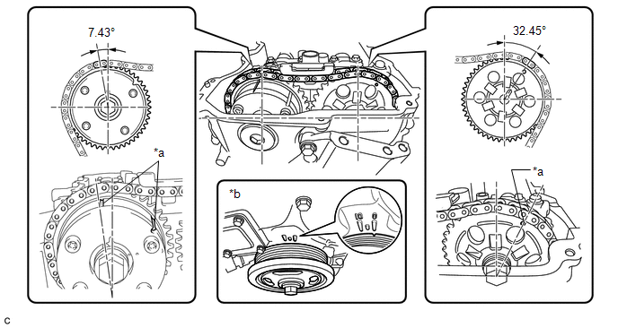
| *a | Timing Mark | *b | No. 1 Cylinder at TDC Compression |
(b) Turn the crankshaft pulley and align its groove with the "0" timing mark of the timing chain cover.
(c) Check that the timing marks of the camshaft timing gear assembly and camshaft timing sprocket are at the positions shown in the illustration.
HINT:
If the timing marks are not as shown, turn the crankshaft one revolution clockwise.
OK:
Timing marks on camshaft timing gear assembly and camshaft timing sprocket are aligned as shown in the illustration.
| NG | | GO TO STEP 9 |
|
| 6. | INSPECT OIL CONTROL VALVE FILTER |
(a) Remove the oil control valve filter.
Click here
(b) Check that the oil control valve filter is not clogged.
OK:
Oil control valve filter is not clogged.
| NG | | REPLACE OIL CONTROL VALVE FILTER |
|
| 7. | REPLACE CAMSHAFT TIMING GEAR ASSEMBLY |
(a) Replace the camshaft timing gear assembly.
Click here
HINT:
Perform "Inspection After Repair" after replacing the camshaft timing gear assembly.
Click here
|
| 8. | CHECK WHETHER DTC OUTPUT RECURS (DTC P0011 OR P0012) |
(a) Connect the Techstream to the DLC3.
(b) Turn the power switch on (IG).
(c) Turn the Techstream on.
(d) Clear the DTCs.
Click here
HINT:
-
P0011 is output:
Clear the DTC not using the Techstream.
-
P0012 is output:
Clear the DTC using the Techstream.
(e) Turn the power switch off and wait for at least 30 seconds.
(f) Turn the power switch on (IG).
(g) Turn the Techstream on.
(h) Put the engine in inspection mode (maintenance mode).
Click here
| Tester Display |
|---|
| Inspection Mode |
(i) Start the engine and warm it up.
(j) Drive the vehicle in accordance with the driving pattern described in the Confirmation Driving Pattern.
(k) Enter the following menus: Powertrain / Engine and ECT / Trouble Codes / Pending.
(l) Read the pending DTCs.
Powertrain > Engine and ECT > Trouble Codes| Result | Proceed to |
|---|---|
| DTCs are not output | A |
| DTC P0011 or P0012 is output | B |
| A | | END |
| B | | REPLACE ECM |
| 9. | CHECK ENGINE MECHANICAL SYSTEM |
(a) Check for mechanical malfunctions that affect the valve timing, such as a jumped tooth or stretching of the timing chain.
| NG | | REPAIR OR REPLACE MALFUNCTIONING PARTS, COMPONENT AND AREA |
|
| 10. | CHECK WHETHER DTC OUTPUT RECURS (DTC P0011 OR P0012) |
(a) Connect the Techstream to the DLC3.
(b) Turn the power switch on (IG).
(c) Turn the Techstream on.
(d) Clear the DTCs.
Click here
HINT:
-
P0011 is output:
Clear the DTC not using the Techstream.
-
P0012 is output:
Clear the DTC using the Techstream.
(e) Turn the power switch off and wait for at least 30 seconds.
(f) Turn the power switch on (IG).
(g) Turn the Techstream on.
(h) Put the engine in inspection mode (maintenance mode).
Click here
| Tester Display |
|---|
| Inspection Mode |
(i) Start the engine and warm it up.
(j) Drive the vehicle in accordance with the driving pattern described in the Confirmation Driving Pattern.
(k) Enter the following menus: Powertrain / Engine and ECT / Trouble Codes / Pending.
(l) Read the pending DTCs.
Powertrain > Engine and ECT > Trouble Codes| Result | Proceed to |
|---|---|
| DTCs are not output | A |
| DTC P0011 or P0012 is output | B |
| A | | CHECK FOR INTERMITTENT PROBLEMS |
| B | | REPLACE ECM |
READ NEXT:
 Crankshaft Position - Camshaft Position Correlation (Bank 1 Sensor A) (P0016)
DESCRIPTION In the VVT (Variable Valve Timing) system, the appropriate intake valve open and close timing is controlled by the ECM. The ECM performs intake valve control by performing the following: 1
Oxygen (A/F) Sensor Heater Control Circuit Low (Bank 1 Sensor 1) (P0031,P0032,P101D)
DESCRIPTION Refer to DTC P2195. Click here HINT:
When any of these DTCs are stored, the ECM enters fail-safe mode. The ECM turns off the air fuel ratio sensor heater in fail-safe mode. Fail-safe
Oxygen Sensor Heater Control Circuit Low (Bank 1 Sensor 2) (P0037,P0038,P0141,P102D)
DESCRIPTION Refer to DTC P0136. Click here HINT: When any of these DTCs are stored, the ECM enters fail-safe mode. The ECM turns off the heated oxygen sensor heater in fail-safe mode. Fail-safe mod
SEE MORE:
Removal
REMOVAL PROCEDURE 1. REMOVE MULTI-DISPLAY ASSEMBLY Click here 2. REMOVE DOOR SCUFF PLATE ASSEMBLY LH Click here 3. REMOVE COWL SIDE TRIM BOARD LH Click here 4. REMOVE REAR CONSOLE ARMREST ASSEMBLY Click here 5. REMOVE UPPER REAR CONSOLE PANEL Click here 6. REMOVE UPPER NO. 1 CONSOLE P
Installation
INSTALLATION PROCEDURE 1. INSTALL ABSORBER CONTROL ECU (a) Install the absorber control ECU with the 2 bolts. Torque: 8.5 N·m {87 kgf·cm, 75 in·lbf} NOTICE:
Avoid any impact to the absorber control ECU.
Do not drop the absorber control ECU. If it is dropped, replace it with a new one.
(b
© 2016-2025 Copyright www.lexunx.com
