Lexus NX: Removal
REMOVAL
PROCEDURE
1. REMOVE MULTI-DISPLAY ASSEMBLY
Click here .gif)
2. REMOVE DOOR SCUFF PLATE ASSEMBLY LH
Click here
3. REMOVE COWL SIDE TRIM BOARD LH
Click here
4. REMOVE REAR CONSOLE ARMREST ASSEMBLY
Click here
5. REMOVE UPPER REAR CONSOLE PANEL
Click here
6. REMOVE UPPER NO. 1 CONSOLE PANEL GARNISH
Click here
7. REMOVE UPPER NO. 2 CONSOLE PANEL GARNISH
Click here
8. REMOVE INSTRUMENT SIDE PANEL LH
Click here
9. REMOVE NO. 1 INSTRUMENT PANEL SAFETY PAD SUB-ASSEMBLY
Click here
10. REMOVE NO. 1 INSTRUMENT PANEL UNDER COVER SUB-ASSEMBLY
Click here
11. REMOVE LOWER NO. 1 INSTRUMENT PANEL FINISH PANEL
Click here
12. REMOVE NO. 1 SWITCH HOLE BASE
Click here
13. REMOVE INSTRUMENT SIDE PANEL RH
Click here
14. REMOVE NO. 2 INSTRUMENT PANEL SAFETY PAD SUB-ASSEMBLY
Click here
15. REMOVE CENTER INSTRUMENT CLUSTER FINISH PANEL ASSEMBLY
Click here
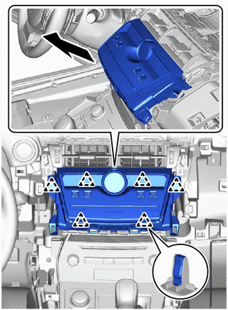
16. REMOVE AIR CONDITIONING CONTROL ASSEMBLY
| (a) Pull the air conditioning control assembly to detach the 6 clips in the direction indicated by the arrow. NOTICE: Do not touch the switch, display or clock parts. |
|
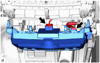
| (b) Disconnect the 2 connectors and remove the air conditioning control assembly. |
|
READ NEXT:
 Installation
INSTALLATION PROCEDURE 1. INSTALL AIR CONDITIONING CONTROL ASSEMBLY (a) Connect the 2 connectors. (b) Attach the 6 clips to install the air conditioning control assembly. NOTICE: Do not touch the s
Components
COMPONENTS ILLUSTRATION *1 AIR CONDITIONER PRESSURE SENSOR - - N*m (kgf*cm, ft.*lbf): Specified torque ● Non-reusable part Compressor oil ND-OIL 11 or equivalent - -
SEE MORE:
Components
COMPONENTS ILLUSTRATION *1 FRONT DOOR INSIDE HANDLE BEZEL PLUG LH *2 FRONT DOOR TRIM BOARD SUB-ASSEMBLY LH *3 FRONT DOOR TRIM COVER LH *4 OUTER MIRROR INSTALL HOLE COVER LH *5 OUTER REAR VIEW MIRROR ASSEMBLY LH *6 POWER WINDOW REGULATOR MASTER SWITCH ASSEMBLY WITH FRONT
Installation
INSTALLATION CAUTION / NOTICE / HINT HINT: Perform "Inspection After Repair" after replacing the fuel injector assembly. Click here PROCEDURE 1. INSTALL FUEL INJECTOR ASSEMBLY HINT: Perform "Inspection After Repair" after replacing the fuel injector assembly. Click here (a) Apply a light coat of
