- DTC judgment completed
- System normal
Lexus NX: Crankshaft Position - Camshaft Position Correlation (Bank 1 Sensor A) (P0016)
Lexus NX Service Manual / Engine & Hybrid System / 2ar-fxe (engine Control) / Sfi System / Crankshaft Position - Camshaft Position Correlation (Bank 1 Sensor A) (P0016)
DESCRIPTION
In the VVT (Variable Valve Timing) system, the appropriate intake valve open and close timing is controlled by the ECM. The ECM performs intake valve control by performing the following: 1) controlling the intake camshaft and camshaft timing oil control valve assembly, and operating the camshaft timing gear assembly; and 2) changing the relative positions of the camshaft and crankshaft.
| DTC No. | Detection Item | DTC Detection Condition | Trouble Area | MIL | Memory |
|---|---|---|---|---|---|
| P0016 | Crankshaft Position - Camshaft Position Correlation (Bank 1 Sensor A) | Deviation in the crankshaft position sensor signal and camshaft position sensor signal (2 trip detection logic). |
| Comes on | DTC stored |
MONITOR DESCRIPTION
To monitor the correlation of the intake camshaft position and crankshaft position, the ECM checks the VVT learned value while the engine is idling. The VVT learned value is calibrated based on the camshaft position and crankshaft position. The intake valve timing is set to the most retarded angle while the engine is idling. If the VVT learned value is out of the specified range in consecutive driving cycles, the ECM illuminates the MIL and stores DTC P0016.
MONITOR STRATEGY
| Related DTCs | P0016: Camshaft timing misaligned at idling |
| Required Sensors/Components (Main) | Camshaft timing gear assembly |
| Required Sensors/Components (Related) | Camshaft position sensor Crankshaft position sensor |
| Frequency of Operation | Continuous |
| Duration | Within 1 minute |
| MIL Operation | 2 driving cycles |
| Sequence of Operation | None |
TYPICAL ENABLING CONDITIONS
| Monitor runs whenever the following DTCs are not stored | None |
| Engine speed | 900 to 1100 rpm |
TYPICAL MALFUNCTION THRESHOLDS
| Either of the following conditions is met | A or B |
| A. VVT learning value at maximum retarded valve timing (bank 1) | Less than 22°CA (Crankshaft Angle) |
| B. VVT learning value at maximum retarded valve timing (bank 1) | More than 47°CA (Crankshaft Angle) |
CONFIRMATION DRIVING PATTERN
- Connect the Techstream to the DLC3.
- Turn the power switch on (IG) and turn the Techstream on.
- Clear the DTCs (even if no DTCs are stored, perform the clear DTC procedure).
- Turn the power switch off and wait for at least 30 seconds.
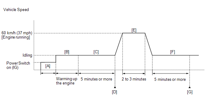
- Turn the power switch on (IG) and turn the Techstream on [A].
-
Put the engine in inspection mode (maintenance mode).
Click here
.gif)
- Start the engine and warm it up until the engine coolant temperature reaches 73°C (163°F) or higher [B].
- Idle the engine for 5 minutes or more [C].
- Enter the following menus: Powertrain / Engine and ECT / Trouble Codes [D].
-
Read the pending DTCs.
HINT:
- If a pending DTC is output, the system is malfunctioning.
- If a pending DTC is not output, perform the following procedure.
- Enter the following menus: Powertrain / Engine and ECT / Utility / All Readiness.
- Input the DTC: P0016.
-
Check the DTC judgment result.
Techstream Display
Description
NORMAL
ABNORMAL
- DTC judgment completed
- System abnormal
INCOMPLETE
- DTC judgment not completed
- Perform driving pattern after confirming DTC enabling conditions
N/A
- Unable to perform DTC judgment
- Number of DTCs which do not fulfill DTC preconditions has reached ECU memory limit
HINT:
- If the judgment result shows NORMAL, the system is normal.
- If the judgment result shows ABNORMAL, the system has a malfunction.
- If the judgment result shows INCOMPLETE or N/A, perform steps [E] through [G].
-
With the engine running, drive the vehicle at 60 km/h (37 mph) for 2 to 3 minutes [E].
CAUTION:
When performing the confirmation driving pattern, obey all speed limits and traffic laws.
HINT:
If the engine stops, further depress the accelerator pedal to restart the engine.
- Idle the engine for 5 minutes or more [F].
- Enter the following menus: Powertrain / Engine and ECT / Trouble Codes [G].
-
Read the pending DTCs.
HINT:
- If a pending DTC is output, the system is malfunctioning.
- If a pending DTC is not output, perform the following procedure.
- Check the DTC judgment result.
-
If the judgment result is INCOMPLETE or N/A and no pending DTC is output, perform a universal trip and check for permanent DTCs.
Click here
HINT:
- If a permanent DTC is output, the system is malfunctioning.
- If no permanent DTC is output, the system is normal.
CAUTION / NOTICE / HINT
HINT:
- The monitor for this DTC detects when the timing chain is shifted by one tooth or more.
- Read freeze frame data using the Techstream. The ECM records vehicle and driving condition information as freeze frame data the moment a DTC is stored. When troubleshooting, freeze frame data can help determine if the vehicle was moving or stationary, if the engine was warmed up or not, if the air fuel ratio was lean or rich, and other data from the time the malfunction occurred.
PROCEDURE
| 1. | CHECK FOR ANY OTHER DTCS OUTPUT (IN ADDITION TO DTC P0016) |
(a) Connect the Techstream to the DLC3.
(b) Turn the power switch on (IG).
(c) Turn the Techstream on.
(d) Enter the following menus: Powertrain / Engine and ECT / Trouble Codes.
(e) Read the DTCs.
Powertrain > Engine and ECT > Trouble Codes| Result | Proceed to |
|---|---|
| DTC P0016 is output | A |
| DTC P0016 and other DTCs are output | B |
HINT:
If any DTCs other than P0016 are output, troubleshoot those DTCs first.
| B | .gif) | GO TO DTC CHART |
|
.gif)
| 2. | PERFORM ACTIVE TEST USING TECHSTREAM (CONTROL THE VVT LINEAR) |
HINT:
If the VVT system can be operated through the Active Test, it can be assumed that the VVT system is operating normally.
(a) Connect the Techstream to the DLC3.
(b) Turn the power switch on (IG) and turn the Techstream on.
(c) Put the engine in inspection mode (maintenance mode).
Click here
| Tester Display |
|---|
| Inspection Mode |
(d) Start the engine.
(e) Enter the following menus: Powertrain / Engine and ECT / Active Test / Control the VVT Linear (Bank 1) / Gas Valve Control / VVT Change Angle #1.
Powertrain > Engine and ECT > Active Test| Active Test Display |
|---|
| Control the VVT Linear (Bank1) |
| Data List Display |
|---|
| VVT Change Angle #1 |
(f) Perform the Active Test. Check that the displacement angle varies.
OK:
Displacement angle varies.
HINT:
- Test not possible with the shift lever in P during charge control. Move the shift lever to N to perform test.
- If the DTCs are stored after the Active Test, clear the DTCs.
| NG | | GO TO STEP 4 |
|
| 3. | CHECK ENGINE MECHANICAL SYSTEM |
(a) Check for mechanical malfunctions that affect the valve timing, such as a jumped tooth or stretching of the timing chain.
| OK | | GO TO STEP 7 |
| NG | | REPAIR OR REPLACE MALFUNCTIONING PARTS, COMPONENT AND AREA |
| 4. | INSPECT CAMSHAFT TIMING OIL CONTROL VALVE ASSEMBLY |
Click here
| NG | | REPLACE CAMSHAFT TIMING OIL CONTROL VALVE ASSEMBLY |
|
| 5. | INSPECT OIL CONTROL VALVE FILTER |
Click here
| NG | | REPLACE OIL CONTROL VALVE FILTER |
|
| 6. | INSPECT CAMSHAFT TIMING GEAR ASSEMBLY |
(a) Inspect the camshaft timing gear assembly.
Click here
HINT:
Perform "Inspection After Repair" after replacing the camshaft timing gear assembly.
Click here
| NG | | REPLACE CAMSHAFT TIMING GEAR ASSEMBLY |
|
| 7. | CHECK WHETHER DTC OUTPUT RECURS (DTC P0016) |
(a) Connect the Techstream to the DLC3.
(b) Turn the power switch on (IG).
(c) Turn the Techstream on.
(d) Clear the DTCs.
Click here
(e) Turn the power switch off and wait for at least 30 seconds.
(f) Turn the power switch on (IG).
(g) Turn the Techstream on.
(h) Put the engine in inspection mode (maintenance mode).
Click here
| Tester Display |
|---|
| Inspection Mode |
(i) Start the engine and warm it up.
(j) Drive the vehicle in accordance with the driving pattern described in the Confirmation Driving Pattern.
(k) Enter the following menus: Powertrain / Engine and ECT / Trouble Codes / Pending.
(l) Read the pending DTCs.
Powertrain > Engine and ECT > Trouble Codes| Result | Proceed to |
|---|---|
| DTCs are not output | A |
| DTC P0016 is output | B |
| A | | CHECK FOR INTERMITTENT PROBLEMS |
| B | | REPLACE ECM |
READ NEXT:
 Oxygen (A/F) Sensor Heater Control Circuit Low (Bank 1 Sensor 1) (P0031,P0032,P101D)
DESCRIPTION Refer to DTC P2195. Click here HINT:
When any of these DTCs are stored, the ECM enters fail-safe mode. The ECM turns off the air fuel ratio sensor heater in fail-safe mode. Fail-safe
Oxygen Sensor Heater Control Circuit Low (Bank 1 Sensor 2) (P0037,P0038,P0141,P102D)
DESCRIPTION Refer to DTC P0136. Click here HINT: When any of these DTCs are stored, the ECM enters fail-safe mode. The ECM turns off the heated oxygen sensor heater in fail-safe mode. Fail-safe mod
EVAP System Tank Vapor Line Restricted/Blocked (P00FE)
DTC SUMMARY DTC No. Detection Item DTC Detection Condition Trouble Area MIL Memory P00FE EVAP System Tank Vapor Line Restricted/Blocked Leak detection pump creates negative pressu
SEE MORE:
Removal
REMOVAL CAUTION / NOTICE / HINT NOTICE:
When the brake pedal is first depressed after replacing the brake pads or pushing back the disc brake piston, DTC C1214 may be output. As there is no malfunction, clear the DTC.
While the auxiliary battery is connected, even if the power switch is off, th
Diagnostic Trouble Code Chart
DIAGNOSTIC TROUBLE CODE CHART Seat Heater System DTC No. Detection Item Link B14C0 Front Right Seat Heat Sensor Circuit B14C1 Front Left Seat Heat Sensor Circuit B14C2 Rear Right Seat Heat Sensor Circuit B14C3 Rear Left Seat Heat Sensor Circuit
© 2016-2025 Copyright www.lexunx.com
