Lexus NX: Center Airbag Sensor Assembly Communication Circuit Malfunction (B1790)
DESCRIPTION
The airbag ECU assembly communication circuit consists of the occupant detection ECU and airbag ECU assembly.
DTC B1790 is stored when a malfunction is detected in the airbag ECU assembly communication circuit.
| DTC No. | Detection Item | DTC Detection Condition | Trouble Area |
|---|---|---|---|
| B1790 | Center Airbag Sensor Assembly Communication Circuit Malfunction | One of the following conditions is met:
|
|
HINT:
- When DTC B1650/32 is stored as a result of troubleshooting the airbag system, perform troubleshooting for DTC B1790 of the occupant classification system.
- Use the Techstream to check for DTCs of the occupant detection ECU, otherwise the DTCs cannot be read.
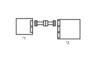
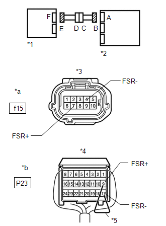
WIRING DIAGRAM
.png)
CAUTION / NOTICE / HINT
NOTICE:
-
After turning the engine switch off, waiting time may be required before disconnecting the cable from the negative (-) auxiliary battery terminal.
Click here
.gif)
-
When disconnecting and reconnecting the auxiliary battery
Click here
HINT:
When disconnecting and reconnecting the battery, there is an automatic learning function that completes learning when the respective system is used.
Click here
-
After replacing the airbag ECU assembly, refer to initialization.
Click here
HINT:
- If troubleshooting (wire harness inspection) is difficult to perform, remove the front RH seat installation bolts to see the undersurface of the seat cushion.
- In the above case, hold the seat so that it does not fall down. Holding the seat for a long period of time may cause problems, such as seat rail deformation. Hold the seat up only for as long as necessary.
PROCEDURE
| 1. | CHECK DTC |
(a) Turn the power switch on (IG), and wait for at least 60 seconds.
(b) Clear the DTCs.
Click here
HINT:
- First clear the DTCs stored in the occupant detection ECU, and then clear the DTCs stored in the airbag ECU assembly.
- Use the Techstream to clear the DTCs of the occupant detection ECU, otherwise the DTCs cannot be cleared.
(c) Turn the power switch off.
(d) Turn the power switch on (IG), and wait for at least 60 seconds.
(e) Check for DTCs.
Click here
HINT:
DTCs other than DTC B1790 may be output at this time, but they are not related to this check.
| DTC B1790 is not output | .gif) | USE SIMULATION METHOD TO CHECK |
|
.gif)
| 2. | CHECK CONNECTION OF CONNECTORS |
(a) Turn the power switch off.
(b) Disconnect the cable from the negative (-) auxiliary battery terminal, and wait for at least 90 seconds.
(c) Check that the connectors are properly connected to the occupant detection ECU and airbag ECU assembly.
| Connectors are not properly connected | | CONNECT CONNECTOR |
|
| 3. | CHECK CONNECTORS |
| (a) Disconnect the connectors from the airbag ECU assembly and occupant detection ECU. |
|
(b) Check that the connectors (on the airbag ECU assembly side and occupant detection ECU side) are not damaged.
| Connectors are deformed or damaged | | REPLACE HARNESS AND CONNECTOR |
|
| 4. | CHECK AIRBAG ECU ASSEMBLY CIRCUIT |
| (a) Connect the cable to the negative (-) auxiliary battery terminal, and wait for at least 2 seconds. |
|
(b) Turn the power switch on (IG).
(c) Measure the voltage according to the value(s) in the table below.
Standard Voltage:
| Tester Connection | Switch Condition | Specified Condition |
|---|---|---|
| f15-7 (FSR+) - Body ground | Power switch on (IG) | Below 1 V |
| f15-4 (FSR-) - Body ground |
(d) Turn the power switch off.
(e) Disconnect the cable from the negative (-) auxiliary battery terminal, and wait for at least 90 seconds.
(f) Using a service wire, connect terminals 9 (FSR+) and 17 (FSR-) of connector B.
NOTICE:
Do not forcibly insert the service wire into the terminals of the connector.
(g) Measure the resistance according to the value(s) in the table below.
Standard Resistance:
| Tester Connection | Condition | Specified Condition |
|---|---|---|
| f15-7 (FSR+) - f15-4 (FSR-) | Always | Below 1 Ω |
(h) Disconnect the service wire from connector B.
(i) Measure the resistance according to the value(s) in the table below.
Standard Resistance:
| Tester Connection | Condition | Specified Condition |
|---|---|---|
| f15-7 (FSR+) - f15-4 (FSR-) | Always | 1 MΩ or higher |
| f15-7 (FSR+) - Body ground | ||
| f15-4 (FSR-) - Body ground |
| NG | | GO TO STEP 10 |
|
| 5. | CHECK DTC |
(a) Connect the connectors to the occupant detection ECU and airbag ECU assembly.
(b) Connect the cable to the negative (-) auxiliary battery terminal, and wait for at least 2 seconds.
(c) Turn the power switch on (IG), and wait for at least 60 seconds.
(d) Clear the DTCs.
Click here
HINT:
- First clear the DTCs stored in the occupant detection ECU, and then clear the DTCs stored in the airbag ECU assembly.
- Use the Techstream to clear the DTCs of the occupant detection ECU, otherwise the DTCs cannot be cleared.
(e) Turn the power switch off.
(f) Turn the power switch on (IG), and wait for at least 60 seconds.
(g) Check for DTCs.
Click here
HINT:
DTCs other than DTC B1790 may be output at this time, but they are not related to this check.
| DTC B1790 is not output | | USE SIMULATION METHOD TO CHECK |
|
| 6. | REPLACE OCCUPANT DETECTION ECU |
(a) Turn the power switch off.
(b) Disconnect the cable from the negative (-) auxiliary battery terminal, and wait for at least 90 seconds.
(c) Replace the occupant detection ECU.
Click here
HINT:
Perform the inspection using parts from a normal vehicle when possible.
|
| 7. | PERFORM ZERO POINT CALIBRATION |
(a) Connect the cable to the negative (-) auxiliary battery terminal, and wait for at least 2 seconds.
(b) Turn the power switch on (IG).
(c) Perform the zero point calibration.
Click here
|
| 8. | PERFORM SENSITIVITY CHECK |
(a) Perform the sensitivity check.
Click here
Standard:
27 to 33 kg (59.5 to 72.8 lb)
|
| 9. | CHECK DTC |
(a) Clear the DTCs.
Click here
HINT:
- First clear the DTCs stored in the occupant detection ECU, and then clear the DTCs stored in the airbag ECU assembly.
- Use the Techstream to clear the DTCs of the occupant detection ECU, otherwise the DTCs cannot be cleared.
(b) Turn the power switch off.
(c) Turn the power switch on (IG), and wait for at least 60 seconds.
(d) Check for DTCs.
Click here
HINT:
DTCs other than DTC B1790 may be output at this time, but they are not related to this check.
| DTC B1790 is not output | | END (OCCUPANT DETECTION ECU WAS DEFECTIVE) |
| DTC B1790 is output | | REPLACE AIRBAG ECU ASSEMBLY |
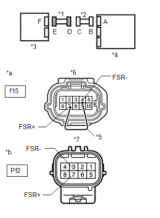
| 10. | CHECK FRONT SEAT WIRE RH |
| (a) Disconnect the front seat wire RH connector from the floor wire. |
|
(b) Connect the cable to the negative (-) auxiliary battery terminal, and wait for at least 2 seconds.
(c) Turn the power switch on (IG).
(d) Measure the voltage according to the value(s) in the table below.
Standard Voltage:
| Tester Connection | Switch Condition | Specified Condition |
|---|---|---|
| Pf2-7 (FSR+) - Body ground | Power switch on (IG) | Below 1 V |
| Pf2-3 (FSR-) - Body ground |
(e) Turn the power switch off.
(f) Disconnect the connector from the occupant detection ECU.
(g) Using a service wire, connect terminals 7 (FSR+) and 4 (FSR-) of connector E.
NOTICE:
Do not forcibly insert the service wire into the terminals of the connector.
(h) Measure the resistance according to the value(s) in the table below.
Standard Resistance:
| Tester Connection | Condition | Specified Condition |
|---|---|---|
| Pf2-7 (FSR+) - Pf2-3 (FSR-) | Always | Below 1 Ω |
(i) Disconnect the service wire from connector E.
(j) Measure the resistance according to the value(s) in the table below.
Standard Resistance:
| Tester Connection | Condition | Specified Condition |
|---|---|---|
| Pf2-7 (FSR+) - Pf2-3 (FSR-) | Always | 1 MΩ or higher |
| Pf2-7 (FSR+) - Body ground | ||
| Pf2-3 (FSR-) - Body ground |
| OK | | REPLACE FLOOR WIRE |
| NG | | REPLACE FRONT SEAT WIRE RH |
READ NEXT:
 Open in Occupant Classification ECU Battery Positive Line (B1794)
DESCRIPTION DTC B1794 is stored when a malfunction is detected in the occupant detection ECU. DTC No. Detection Item DTC Detection Condition Trouble Area B1794 Open in Occupant Classifi
Occupant Classification ECU Malfunction (B1795)
DESCRIPTION DTC B1795 is stored when a malfunction is detected in the occupant detection ECU. Troubleshoot DTC B1771 first when both DTCs B1771 and B1795 are present. DTC No. Detection Item DTC
Sleep Operation Failure of Occupant Classification ECU (B1796)
DESCRIPTION During sleep mode, the occupant detection ECU monitors the condition of each sensor while the power switch is off. In this mode, if the occupant detection ECU detects an internal malfuncti
SEE MORE:
Components
COMPONENTS ILLUSTRATION *1 QUARTER OUTSIDE MOULDING SUB-ASSEMBLY LH *2 REAR BUMPER SIDE SEAL LH *3 REAR TIRE PRESSURE MONITOR INITIATOR *4 REAR WHEEL HOUSE FRONT PLATE LH *5 REAR WHEEL HOUSE LINER LH - - N*m (kgf*cm, ft.*lbf): Specified torque - -
Installation
INSTALLATION CAUTION / NOTICE / HINT HINT: A bolt without a torque specification is shown in the standard bolt chart. Click here PROCEDURE 1. INSTALL ELECTRICAL KEY AND TPMS RECEIVER ASSEMBLY (a) Connect the connector. (b) Attach the 2 guides and Install the electrical key and TPMS receiver assemb
