Lexus NX: Clearance Warning Buzzer (for Rear Side)
Components
COMPONENTS
ILLUSTRATION
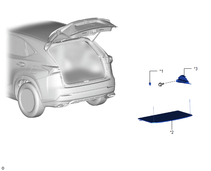
| *1 | CLEARANCE WARNING BUZZER NO. 2 | *2 | TONNEAU COVER ASSEMBLY |
| *3 | UPPER DECK TRIM SIDE BOARD RH | - | - |
Removal
REMOVAL
PROCEDURE
1. REMOVE TONNEAU COVER ASSEMBLY
Click here .gif)
2. REMOVE UPPER DECK TRIM SIDE BOARD RH
HINT:
Use the same procedure described for the LH side.
Click here
3. REMOVE CLEARANCE WARNING BUZZER NO. 2
| (a) Disconnect the connector. |
|
(b) Using a clip remover, detach the clamp and remove the clearance warning buzzer No. 2.
Installation
INSTALLATION
PROCEDURE
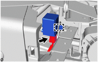
1. INSTALL CLEARANCE WARNING BUZZER NO. 2
(a) Attach the clamp to install the clearance warning buzzer No. 2.
| (b) Connect the connector. |
|
.png)
2. INSTALL UPPER DECK TRIM SIDE BOARD RH
HINT:
Use the same procedure described for the LH side.
Click here .gif)
3. INSTALL TONNEAU COVER ASSEMBLY
Click here
READ NEXT:
 Components
COMPONENTS ILLUSTRATION *1 DECK FLOOR BOX LH *2 NO. 3 DECK BOARD SUB-ASSEMBLY *3 REAR DECK FLOOR BOX *4 NEGATIVE AUXILIARY BATTERY TERMINAL N*m (kgf*cm, ft.*lbf): Specified
Removal
REMOVAL PROCEDURE 1. PRECAUTION NOTICE: After the power switch is turned off, there may be a waiting time before disconnecting the negative (-) auxiliary battery terminal. Click here 2. REMOVE NO. 3
SEE MORE:
Diagnosis System
DIAGNOSIS SYSTEM DIAGNOSIS FUNCTION (a) The road sign assist system displays a warning message on the multi-information display to inform the driver that the system is unavailable when it is malfunctioning. Warning Message Details DTC/RoB "RSA Malfunction Visit Your Dealer" is displayed
Power Window Switch Malfunction (B2312)
DESCRIPTION The power window regulator motor assemblies are operated by the multiplex network master switch assembly, power window regulator switch assembly or rear power window regulator switch assemblies. The power window regulator motor assemblies have motor, regulator and ECU functions. This DTC
