Lexus NX: Glass Temperature Sensor Circuit (B14A8)
DESCRIPTION
The air conditioning amplifier assembly detects the windshield glass surface temperature from this circuit. The air conditioning amplifier assembly applies voltage to the air conditioning thermistor assembly (glass temperature sensor). As the windshield glass surface temperature rises, the resistance decreases. The air conditioning amplifier assembly detects the change in resistance as the windshield glass surface temperature changes.
The glass temperature sensor is integrated with the air conditioning thermistor assembly.
| DTC No. | Detection Item | DTC Detection Condition | Trouble Area | Memory | Note |
|---|---|---|---|---|---|
| B14A8 | Glass Temperature Sensor Circuit | Open or short in glass temperature sensor circuit |
| Memorized (4 seconds or more)* | - |
- *: The air conditioning amplifier assembly stores this DTC if the malfunction has occurred for the period of time indicated in the brackets.
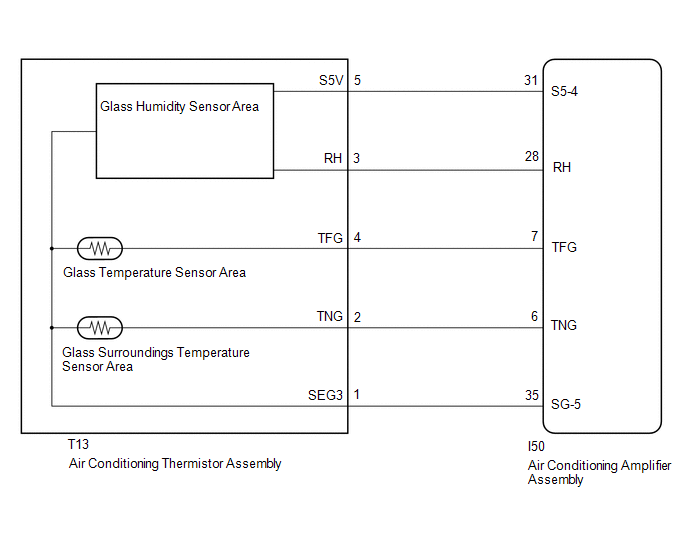
WIRING DIAGRAM
CAUTION / NOTICE / HINT
HINT:
The air conditioning thermistor assembly must be replaced if the glass temperature sensor is malfunctioning.
PROCEDURE
| 1. | READ VALUE USING TECHSTREAM |
(a) Connect the Techstream to the DLC3.
(b) Turn the power switch on (IG).
(c) Turn the Techstream on.
(d) Enter the following menus: Body Electrical / Air Conditioner / Data List.
(e) Check the value(s) by referring to the table below.
Body Electrical > Air Conditioner > Data List| Tester Display | Measurement Item | Range | Normal Condition | Diagnostic Note |
|---|---|---|---|---|
| Glass Temperature | Glass temperature | Min.: -327.68°C (-557.82°F) Max.: 327.67°C (621.81°F) | Actual glass temperature is displayed | - |
| Tester Display |
|---|
| Glass Temperature |
OK:
The display is as specified in the normal condition column.
| OK | .gif) | REPLACE AIR CONDITIONING AMPLIFIER ASSEMBLY |
|
.gif)
| 2. | INSPECT AIR CONDITIONING THERMISTOR ASSEMBLY (GLASS TEMPERATURE SENSOR) |
(a) Remove the air conditioning thermistor assembly (glass temperature sensor).
Click here .gif)
(b) Inspect the air conditioning thermistor assembly (glass temperature sensor).
Click here
| NG | | REPLACE AIR CONDITIONING THERMISTOR ASSEMBLY (GLASS TEMPERATURE SENSOR) |
|
| 3. | CHECK HARNESS AND CONNECTOR (AIR CONDITIONING THERMISTOR ASSEMBLY [GLASS TEMPERATURE SENSOR] - AIR CONDITIONING AMPLIFIER ASSEMBLY) |
(a) Disconnect the T13 air conditioning temperature sensor (glass temperature sensor) connector.
(b) Disconnect the I50 air conditioning amplifier assembly connector.
(c) Measure the resistance according to the value(s) in the table below.
Standard Resistance:
| Tester Connection | Condition | Specified Condition |
|---|---|---|
| T13-4 (TFG) - I50-7 (TFG) | Always | Below 1 Ω |
| T13-1 (SEG3) - I50-35 (SG-5) | Always | Below 1 Ω |
| T13-4 (TFG) or I50-7 (TFG) - Body ground | Always | 10 kΩ or higher |
| T13-1 (SEG3) or I50-35 (SG-5) - Body ground | Always | 10 kΩ or higher |
| OK | | REPLACE AIR CONDITIONING AMPLIFIER ASSEMBLY |
| NG | | REPAIR OR REPLACE HARNESS OR CONNECTOR |
READ NEXT:
 Glass Surroundings Temperature Sensor Circuit (B14A9)
DESCRIPTION The air conditioning amplifier assembly detects the temperature of the area near the windshield glass using this circuit. The air conditioning amplifier assembly applies voltage to the air
Glass Humidity Sensor Circuit (B14AA)
DESCRIPTION The air conditioning thermistor assembly (glass humidity sensor) detects cabin humidity. The voltage of the air conditioning thermistor assembly (glass humidity sensor) changes in accordan
Lost Communication with Front Panel LIN (B14B2)
DESCRIPTION The air conditioning control assembly communicates with the air conditioning amplifier assembly through the LIN communication system. If the LIN communication system malfunctions, the air
SEE MORE:
Data List / Active Test
DATA LIST / ACTIVE TEST DATA LIST NOTICE:
In the table below, the values listed under "Normal Condition" are reference values. Do not depend solely on these reference values when deciding whether a part is faulty or not.
When using the Techstream with the power switch off, connect the Techstrea
Terminals Of Ecu
TERMINALS OF ECU TERMINAL INSPECTION *a Component without harness connected (Steering Lock ECU (Steering Lock Actuator Assembly)) - - (a) Measure the voltage and resistance according to the value(s) in the table below. Terminal No. (Symbol) Input/Output Wiring Color Terminal De
