Lexus NX: Communication Malfunction (A/C Inverter Local) (B1498)
DESCRIPTION
The hybrid vehicle control ECU and compressor with motor assembly communicate via a direct line. Compressor control is stopped and this DTC is stored if communication information is cut off or abnormal information occurs.
This DTC is also detected if high-voltage power supplied from the inverter with converter assembly to the compressor control circuit is shut off.
This DTC will be stored as a history DTC.
| DTC No. | Detection Item | DTC Detection Condition | Trouble Area | Memory | Note |
|---|---|---|---|---|---|
| B1498 | Communication Malfunction (A/C Inverter Local) |
|
| Memorized | - |
WIRING DIAGRAM
.png)
CAUTION / NOTICE / HINT
CAUTION:
- Wear insulated gloves and pull out the service plug grip before inspection as procedures may require disconnecting high-voltage connectors. Carry the removed service plug in your pocket to prevent other technicians from accidentally reconnecting it while you are servicing the vehicle.
- Do not touch the high-voltage connectors or terminals for 10 minutes after the service plug grip is removed.
NOTICE:
- Inspect the fuses for circuits related to this system before performing the following procedure.
-
After the power switch is turned off, there may be a waiting time before disconnecting the negative (-) auxiliary battery terminal.
Click here
.gif)
-
When disconnecting and reconnecting the auxiliary battery terminal
Click here
HINT:
When disconnecting and reconnecting the auxiliary battery, there is an automatic learning function that completes learning when the respective system is used.
Click here
- The hybrid control system and air conditioning system output DTCs separately. Perform troubleshooting for the hybrid control system first if DTCs from these systems are output simultaneously.
- Depending on the timing of the power supply to the 12 V power supply circuit and high-voltage circuit when the power switch is turned on (READY), an abnormal information signal may be output, causing this DTC to be stored. If the output DTC is a code that was memorized in the past, check the fuses and wire harnesses. If there is no malfunction, clear the DTC.
PROCEDURE
| 1. | CHECK CAN COMMUNICATION SYSTEM |
(a) Using the Techstream, check if the CAN communication system is functioning normally.
Click here
| Result | Proceed to |
|---|---|
| CAN communication system DTCs are not output | A |
| CAN communication system DTCs are output | B |
| B | .gif) | GO TO CAN COMMUNICATION SYSTEM |
|
.gif)
| 2. | CHECK FOR DTC |
(a) Check if hybrid control system DTCs are output.
Click here
| Result | Proceed to |
|---|---|
| DTCs are not output | A |
| Only DTC P3108-536 is output | |
| DTCs other than P3108 are output | B |
| B | | GO TO HYBRID CONTROL SYSTEM |
|
| 3. | CHECK HARNESS AND CONNECTOR (COMPRESSOR WITH MOTOR ASSEMBLY - BATTERY AND BODY GROUND) |
CAUTION:
Do not disconnect the connector on the high-voltage side.
| (a) Disconnect the compressor with motor assembly connector. NOTICE: Do not allow any foreign matter or water to enter the compressor with motor assembly. |
|
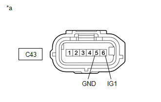
(b) Measure the resistance according to the value(s) in the table below.
Standard Resistance:
| Tester Connection | Condition | Specified Condition |
|---|---|---|
| C43-5 (GND) - Body ground | Always | Below 1 Ω |
(c) Measure the voltage according to the value(s) in the table below.
Standard Voltage:
| Tester Connection | Switch Condition | Specified Condition |
|---|---|---|
| C43-6 (IG1) - C43-5 (GND) | Power switch on (IG) | 11 to 14 V |
| C43-6 (IG1) - C43-5 (GND) | Power switch off | Below 1 V |
| NG | | REPAIR OR REPLACE HARNESS OR CONNECTOR |
|
| 4. | CHECK HARNESS AND CONNECTOR (HYBRID VEHICLE CONTROL ECU - COMPRESSOR WITH MOTOR ASSEMBLY) |
(a) Disconnect the A61 hybrid vehicle control ECU connector.
(b) Disconnect the C43 compressor with motor assembly connector.
NOTICE:
Do not allow any foreign matter or water to enter the compressor with motor assembly.
(c) Measure the resistance according to the value(s) in the table below.
Standard Resistance:
| Tester Connection | Condition | Specified Condition |
|---|---|---|
| C43-1 (CLK) - A61-10 (CLK) | Always | Below 1 Ω |
| C43-2 (DIN) - A61-9 (ITE) | Always | Below 1 Ω |
| C43-3 (DOUT) - A61-8 (ETI) | Always | Below 1 Ω |
| C43-1 (CLK) or A61-10 (CLK) - Body ground | Always | 10 kΩ or higher |
| C43-2 (DIN) or A61-9 (ITE) - Body ground | Always | 10 kΩ or higher |
| C43-3 (DOUT) or A61-8 (ETI) - Body ground | Always | 10 kΩ or higher |
| NG | | REPAIR OR REPLACE HARNESS OR CONNECTOR |
|
| 5. | INSPECT HIGH VOLTAGE FUSE |
CAUTION:
Be sure to wear insulated gloves.
(a) Turn the power switch off.
(b) Remove the service plug grip.
Click here
CAUTION:
Do not touch the high-voltage connectors or terminals for 10 minutes after the service plug grip is removed.
NOTICE:
After removing the service plug grip, turning the power switch on (READY) may cause a malfunction. Do not turn the power switch on (READY) with the service plug grip removed.
(c) Remove the connector cover assembly.
Click here
NOTICE:
Be sure to prevent foreign matter or water from entering the inverter with converter assembly.
| (d) Check that bolts A and B are tightened securely. |
|
.png)
(e) Measure the resistance according to the value(s) in the table below.
Standard Resistance:
| Tester Item (Tester Connection) | Condition | Specified Condition |
|---|---|---|
| High voltage fuse (A - B) | Always | Below 1 Ω |
| NG | | REPLACE HIGH VOLTAGE FUSE |
|
| 6. | INSPECT ENGINE WIRE |
CAUTION:
Be sure to wear insulated gloves.
(a) Disconnect the C47 and C46 engine wire connectors.
Click here
NOTICE:
Do not allow any foreign matter or water to enter the compressor with motor assembly.
(b) Measure the resistance according to the value(s) in the table below.
Standard Resistance:
| Tester Connection | Condition | Specified Condition |
|---|---|---|
| C46-1 (PE) - C47-1 (ACPE) | Always | Below 1 Ω |
| C46-2 (PB) - C47-2 (ACPB) | Always | Below 1 Ω |
| C46-1 (PE) or C47-1 (ACPE) - Body ground | Always | 10 kΩ or higher |
| C46-2 (PB) or C47-2 (ACPB) - Body ground | Always | 10 kΩ or higher |
| NG | | REPLACE ENGINE WIRE |
|
| 7. | REPLACE COMPRESSOR WITH MOTOR ASSEMBLY |
(a) Replace the compressor with motor assembly.
Click here
HINT:
Since the compressor with motor assembly cannot be inspected while it is removed from the vehicle, replace the compressor with motor assembly with a new or known good one and check that the condition returns to normal.
(b) Check for DTCs.
Body Electrical > Air Conditioner > Trouble Codes| Result | Proceed to |
|---|---|
| DTC B1498 is not output | A |
| DTC B1498 is output | B |
| A | | END (COMPRESSOR WITH MOTOR ASSEMBLY IS DEFECTIVE) |
| B | | REPLACE HYBRID VEHICLE CONTROL ECU |
READ NEXT:
 Glass Temperature Sensor Circuit (B14A8)
DESCRIPTION The air conditioning amplifier assembly detects the windshield glass surface temperature from this circuit. The air conditioning amplifier assembly applies voltage to the air conditioning
Glass Surroundings Temperature Sensor Circuit (B14A9)
DESCRIPTION The air conditioning amplifier assembly detects the temperature of the area near the windshield glass using this circuit. The air conditioning amplifier assembly applies voltage to the air
Glass Humidity Sensor Circuit (B14AA)
DESCRIPTION The air conditioning thermistor assembly (glass humidity sensor) detects cabin humidity. The voltage of the air conditioning thermistor assembly (glass humidity sensor) changes in accordan
SEE MORE:
Parts Location
PARTS LOCATION ILLUSTRATION *A w/ Power Back Door System *B w/o Power Back Door System *1 DOOR CONTROL SWITCH *2 MULTIPLEX NETWORK MASTER SWITCH ASSEMBLY *3 FRONT DOOR LOCK ASSEMBLY LH *4 FRONT DOOR LOCK ASSEMBLY RH *5 REAR DOOR LOCK ASSEMBLY LH *6 REAR DOOR L
Passenger Side Buckle Switch Circuit Malfunction (B1771)
DESCRIPTION The front passenger side buckle switch circuit consists of the occupant detection ECU and front seat inner belt assembly RH. DTC B1771 is stored when a malfunction is detected in the front passenger side buckle switch circuit. Troubleshoot DTC B1771 first when DTCs B1771 and B1795 are ou
