Lexus NX: Components
COMPONENTS
ILLUSTRATION
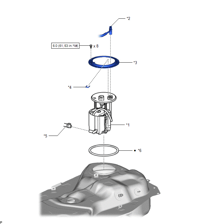
| *1 | FUEL SUCTION TUBE ASSEMBLY | *2 | FUEL TANK MAIN TUBE SUB-ASSEMBLY |
| *3 | FUEL TANK VENT TUBE SET PLATE | *4 | TUBE JOINT CLIP |
| *5 | FUEL HOSE | *6 | GASKET |
.png) | N*m (kgf*cm, ft.*lbf): Specified torque | ● | Non-reusable part |
ILLUSTRATION
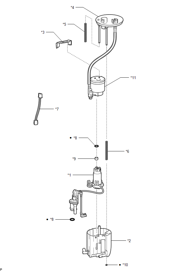
| *1 | FUEL PUMP ASSEMBLY WITH FILTER | *2 | NO. 1 FUEL SUB-TANK |
| *3 | NO. 1 FUEL SUCTION SUPPORT | *4 | FUEL SUCTION PLATE SUB-ASSEMBLY |
| *5 | NO. 2 FUEL TANK CUSHION | *6 | NO. 3 FUEL TANK CUSHION |
| *7 | FUEL PUMP HARNESS | *8 | O-RING |
| *9 | FUEL PUMP SPACER | *10 | FUEL TANK PIPE SETTING HOLDER |
| *11 | FUEL FILTER ASSEMBLY | - | - |
| ● | Non-reusable part | - | - |
READ NEXT:
 Removal
REMOVAL PROCEDURE 1. REMOVE FUEL TANK ASSEMBLY Click here 2. DISCONNECT FUEL TANK MAIN TUBE SUB-ASSEMBLY (a) Remove the tube joint clip, then disconnect the fuel tank main tube sub-assembly from
Disassembly
DISASSEMBLY CAUTION / NOTICE / HINT NOTICE: Do not try to remove the black nylon tube as it is welded to the fuel suction tube assembly. Click here PROCEDURE 1. REMOVE NO. 1 FUEL SUB-TANK (a) Di
Inspection
INSPECTION PROCEDURE 1. INSPECT FUEL PUMP ASSEMBLY WITH FILTER (a) Check the resistance. (1) Measure the resistance according to the value(s) in the table below. Standard Resistance: Tester Con
SEE MORE:
Removal
REMOVAL PROCEDURE 1. REMOVE REAR SEAT ASSEMBLY (a) for Manual Seat: Click here (b) for Power Seat: Click here 2. REMOVE REAR FLOOR FINISH PLATE Click here 3. DISCONNECT REAR DOOR OPENING TRIM WEATHERSTRIP RH Click here 4. REMOVE UPPER DECK TRIM SIDE BOARD RH Click here 5. REMOVE ROPE HOO
Motor Electronics Coolant Temperature Sensor Circuit Range / Performance (P0A01-726,P0A04-725)
DTC SUMMARY MALFUNCTION DESCRIPTION These DTCs indicate the temperature sensor value is abnormal. The cause of this malfunction may be one of the following: Area Main Malfunction Description Step Inverter low-voltage circuit The connectors are not connected properly 2 Hybrid cooli
© 2016-2026 Copyright www.lexunx.com
