Lexus NX: Removal
REMOVAL
PROCEDURE
1. REMOVE REAR SEAT ASSEMBLY
(a) for Manual Seat:
Click here .gif)
(b) for Power Seat:
Click here
2. REMOVE REAR FLOOR FINISH PLATE
Click here
3. DISCONNECT REAR DOOR OPENING TRIM WEATHERSTRIP RH
Click here
4. REMOVE UPPER DECK TRIM SIDE BOARD RH
Click here
5. REMOVE ROPE HOOK ASSEMBLY
Click here
6. REMOVE LUGGAGE HOLD BELT STRIKER ASSEMBLY
Click here
7. REMOVE NO. 1 LUGGAGE COMPARTMENT TRIM HOOK
Click here
8. REMOVE DECK TRIM SIDE PANEL ASSEMBLY RH
Click here
9. REMOVE BLIND SPOT MONITOR BUZZER
| (a) Disconnect the connector. |
|
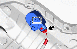
(b) Detach the clamp and remove the blind spot monitor buzzer.
READ NEXT:
 Installation
INSTALLATION PROCEDURE 1. INSTALL BLIND SPOT MONITOR BUZZER (a) Attach the clamp to install the blind spot monitor buzzer. (b) Connect the connector. 2. INSTALL DECK TRIM SIDE PANEL ASSEMBLY RH Click
Television Camera (for Front)
ComponentsCOMPONENTS ILLUSTRATION *1 FRONT TELEVISION CAMERA ASSEMBLY - - RemovalREMOVAL PROCEDURE 1. PRECAUTION Click here 2. REMOVE FRONT BUMPER COVER (a) for Sport Package: Click h
SEE MORE:
Dtc Check / Clear
DTC CHECK / CLEAR CHECK DTC (CHECK USING Techstream) (a) Connect the Techstream to the DLC3. (b) Turn the power switch on (IG) and wait for 90 seconds. (c) Turn the Techstream on. (d) Enter the following menus: Body Electrical / Navigation System / Trouble Codes. Body Electrical > Navigation Syst
Removal
REMOVAL PROCEDURE 1. PRECAUTION CAUTION: Be sure to read Precoution thoroughly before serving. Click here NOTICE: After turning the power switch off, there may be a waiting time before disconnecting the negative (-) auxiliary battery terminal. Click here 2. DISABLE BRAKE CONTROL (a) Wait for at
© 2016-2026 Copyright www.lexunx.com
