Lexus NX: Components
COMPONENTS
ILLUSTRATION
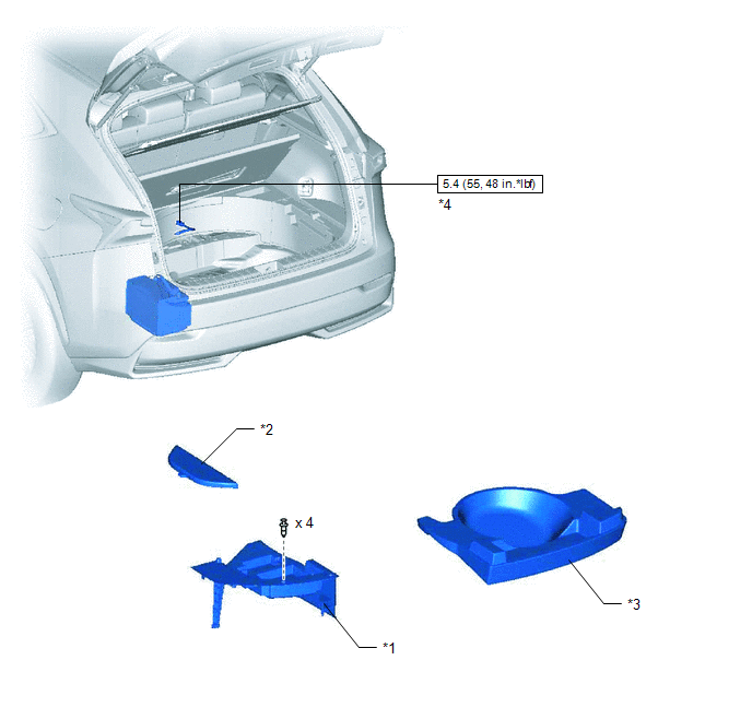
| *1 | DECK FLOOR BOX LH | *2 | NO. 3 DECK BOARD SUB-ASSEMBLY |
| *3 | REAR DECK FLOOR BOX | *4 | NEGATIVE AUXILIARY BATTERY TERMINAL |
.png) | N*m (kgf*cm, ft.*lbf): Specified torque | - | - |
ILLUSTRATION
.png)
| *1 | BATTERY SERVICE HOLE COVER | *2 | HYBRID BATTERY SERVICE PLUG COVER |
| *3 | SERVICE PLUG GRIP | - | - |
| | N*m (kgf*cm, ft.*lbf): Specified torque | - | - |
ILLUSTRATION
.png)
| *1 | CONNECTOR COVER ASSEMBLY | *2 | INVERTER RESERVE TANK ASSEMBLY |
| *3 | WIRE HARNESS | - | - |
| | N*m (kgf*cm, ft.*lbf): Specified torque | - | - |
ILLUSTRATION
| *1 | HYBRID BATTERY JUNCTION BLOCK ASSEMBLY | *2 | NO. 2 HYBRID VEHICLE BATTERY SHIELD REINFORCEMENT |
| *3 | NO. 2 FRAME WIRE | *4 | BATTERY COVER LOCK STRIKER |
| | N*m (kgf*cm, ft.*lbf): Specified torque | - | - |
READ NEXT:
 Removal
REMOVAL PROCEDURE 1. PRECAUTION Click here 2. CHECK FOR DTC (a) Check for DTCs. Click here NOTICE: Confirm that P0AA6 (Hybrid Battery Voltage System Isolation Fault) is not output before removing
Inspection
INSPECTION PROCEDURE 1. INSPECT HV BATTERY JUNCTION BLOCK ASSEMBLY (a) Inspect SMRB: (1) Measure the resistance according to the value(s) in the table below. Standard Resistance: Tester Connect
Installation
INSTALLATION PROCEDURE 1. INSTALL HV BATTERY JUNCTION BLOCK ASSEMBLY CAUTION: Wear insulated gloves and use insulated tools. (a) Install the hybrid battery junction block assembly with the 3 nuts. Tor
SEE MORE:
Back Door Closer Switch Malfunction (B2251)
DESCRIPTION The multiplex network door ECU receives signals from the latch switch, initial switch, pawl switch and back door courtesy switch, which are built into the back door lock assembly. Based on these switch signals, the latch position of the back door lock assembly is determined. DTC No.
Operation Check
OPERATION CHECK AUTOMATIC LIGHT CONTROL SYSTEM OPERATION CHECK (a) Turn the power switch on (IG). (b) Turn the headlight dimmer switch to the AUTO position. (c) Cover the automatic light control sensor. (d) Check that the taillights and low beam headlights come on. (e) Uncover the automatic light co
© 2016-2026 Copyright www.lexunx.com
