Lexus NX: Components
COMPONENTS
ILLUSTRATION
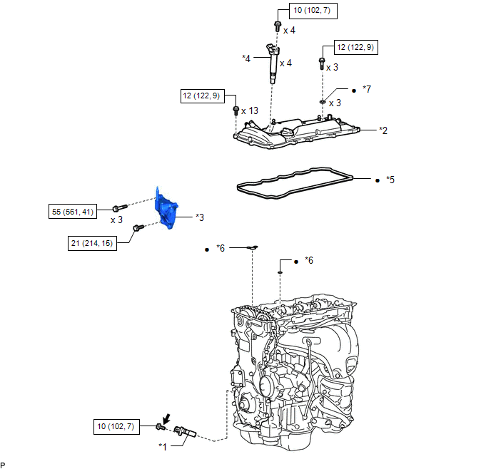
| *1 | CRANKSHAFT POSITION SENSOR | *2 | CYLINDER HEAD COVER SUB-ASSEMBLY |
| *3 | ENGINE MOUNTING BRACKET RH | *4 | IGNITION COIL ASSEMBLY |
| *5 | CYLINDER HEAD COVER GASKET | *6 | GASKET |
| *7 | SEAL WASHER | - | |
.png) | N*m (kgf*cm, ft.*lbf): Specified torque | ● | Non-reusable part |
.png) | Toyota Genuine Adhesive 1324, Three Bond 1324 or equivalent | ★ | Precoated part |
ILLUSTRATION
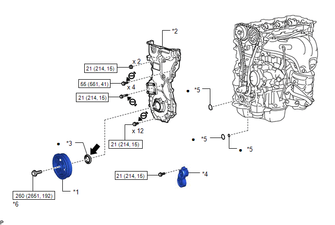
| *1 | CRANKSHAFT PULLEY ASSEMBLY | *2 | TIMING CHAIN COVER ASSEMBLY |
| *3 | TIMING CHAIN COVER OIL SEAL | *4 | V-RIBBED BELT TENSIONER ASSEMBLY |
| *5 | GASKET | *6 | CRANKSHAFT PULLEY SET BOLT |
| | N*m (kgf*cm, ft.*lbf): Specified torque | ● | Non-reusable part |
| | MP grease | .png) | Do not apply lubricants to the threads |
READ NEXT:
 Removal
REMOVAL CAUTION / NOTICE / HINT NOTICE: Do not remove the oil pump and oil pump relief valve from the timing chain cover assembly. PROCEDURE 1. REMOVE ENGINE AND TRANSAXLE Click here 2. REMOVE ENG
Installation
INSTALLATION PROCEDURE 1. INSTALL TIMING CHAIN COVER ASSEMBLY (a) Apply a light coat of engine oil to the 3 new gaskets. (b) Install the 3 gaskets to the stiffening crankcase assembly. (c) Align th
SEE MORE:
Data List / Active Test
DATA LIST / ACTIVE TEST DATA LIST HINT: Using the Techstream to read the Data List allows the values or states of switches, sensors, actuators and other items to be read without removing any parts. This non-intrusive inspection can be very useful because intermittent conditions or signals may be dis
Drive Motor "A" Inverter Performance (P0A78-113)
DTC SUMMARY MALFUNCTION DESCRIPTION This DTC indicates that a large current flowed through the inverter for the motor. The cause of this malfunction may be one of the following: Area Main Malfunction Description Step Inverter low-voltage circuit The connectors are not connected properly
© 2016-2026 Copyright www.lexunx.com
