
Lexus NX: Removal
REMOVAL
CAUTION / NOTICE / HINT
NOTICE:
Do not remove the oil pump and oil pump relief valve from the timing chain cover assembly.
PROCEDURE
1. REMOVE ENGINE AND TRANSAXLE
Click here .gif)
2. REMOVE ENGINE WIRE
Click here
3. REMOVE IGNITION COIL ASSEMBLY
Click here
4. REMOVE CYLINDER HEAD COVER SUB-ASSEMBLY
Click here
5. REMOVE CRANKSHAFT POSITION SENSOR
Click here
6. REMOVE CRANKSHAFT PULLEY ASSEMBLY
Click here
7. REMOVE ENGINE MOUNTING BRACKET RH
Click here
8. REMOVE V-RIBBED BELT TENSIONER ASSEMBLY
Click here
9. REMOVE TIMING CHAIN COVER ASSEMBLY
| (a) Remove the 2 nuts and 17 bolts from the timing chain cover assembly. |
|
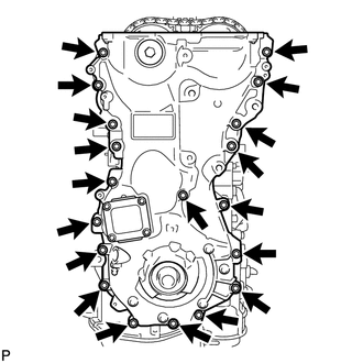
(b) Using a screwdriver wrapped in protective tape, remove the timing chain cover assembly by prying the points in the illustration.
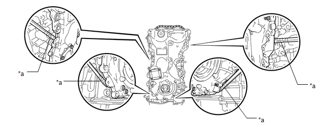
| *a | Protective Tape | - | - |
NOTICE:
Do not damage the contacting surfaces of the timing chain cover assembly, camshaft housing sub-assembly, cylinder head sub-assembly, stiffening crankcase assembly and cylinder block.
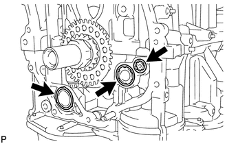
| (c) Remove the 3 gaskets from the stiffening crankcase assembly. |
|
10. REMOVE TIMING CHAIN COVER OIL SEAL
Click here
READ NEXT:
 Installation
INSTALLATION PROCEDURE 1. INSTALL TIMING CHAIN COVER ASSEMBLY (a) Apply a light coat of engine oil to the 3 new gaskets. (b) Install the 3 gaskets to the stiffening crankcase assembly. (c) Align th
Power Switch
ComponentsCOMPONENTS ILLUSTRATION *1 INSTRUMENT CLUSTER FINISH PANEL SUB-ASSEMBLY *2 POWER SWITCH RemovalREMOVAL PROCEDURE 1. REMOVE INSTRUMENT CLUSTER FINISH PANEL SUB-ASSEMBLY Click h
SEE MORE:
Customize Parameters
CUSTOMIZE PARAMETERS CUSTOMIZE LANE TRACING ASSIST SYSTEM (w/ Lane Centering Function) NOTICE:
When the customer requests a change in a function, first make sure that the function can be customized.
Be sure to make a note of the current settings before customizing.
When troubleshooting a func
DC/DC Converter Voltage Sensor "A" Low (P0E33-589,P0E34-590)
DESCRIPTION The MG ECU, which is built into the inverter with converter assembly, detects pre-boosting high voltage (VL) using the voltage sensor in the boost converter to control boosting. The MG ECU also monitors the boost converter voltage sensor signal line and detects malfunctions. DTC No.
