Lexus NX: Installation
INSTALLATION
PROCEDURE
1. INSTALL TIMING CHAIN COVER ASSEMBLY
(a) Apply a light coat of engine oil to the 3 new gaskets.
(b) Install the 3 gaskets to the stiffening crankcase assembly.
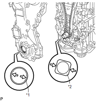
| (c) Align the positions of the drive rotor spline and crankshaft timing sprocket as shown in the illustration. |
|
(d) Apply a coating of seal packing to the timing chain cover assembly at the points shown in the illustration.
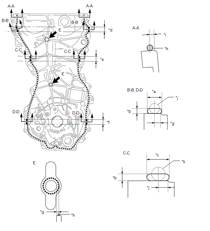
| *a | 7.0 mm (0.276 in.) or more | *b | 3.0 mm (0.118 in.) or more |
| *c | 13.0 mm (0.512 in.) or more | *d | 28 mm (1.10 in.) |
| *e | 25 mm (0.984 in.) | *f | 26 mm (1.02 in.) |
| *g | 3.0 mm (0.118 in.) | *h | 2.5 to 3.5 mm (0.0984 to 0.138 in.) |
| *i | 2.5 mm (0.0984 in.) | *j | 5.0 mm (0.197 in.) |
| *k | 7.0 mm (0.276 in.) | - | - |
Seal packing:
Toyota Genuine Seal Packing Black, Three Bond 1207B or equivalent.
Seal Packing Application Specification:
| Line Type and Area | Seal Packing Diameter | Application Area | Seal Packing Application Length |
|---|---|---|---|
| Coating Width | |||
| Dashed Line | 2.5 to 3.5 mm (0.0984 to 0.138 in.) | 2.5 mm (0.0984 in.) | - |
| - | |||
| A - A | 2.5 to 3.5 mm (0.0984 to 0.138 in.) | 2.5 mm (0.0984 in.) | - |
| - | |||
| B - B | 5.0 mm (0.197 in.) | 3.0 mm (0.118 in.) | 28 mm (1.10 in.) |
| Width 7.0 mm (0.276 in.) or more Thickness 3.0 mm (0.118 in.) or more | |||
| C - C | 7.0 mm (0.276 in.) | 5.0 mm (0.197 in.) | 25 mm (0.984 in.) |
| Width 13 mm (0.512 in.) or more Thickness 3.0 mm (0.118 in.) or more | |||
| D - D | 5.0 mm (0.197 in.) | 3.0 mm (0.118 in.) | 26 mm (1.02 in.) |
| Width 7.0 mm (0.276 in.) or more Thickness 3.0 mm (0.118 in.) or more | |||
| E | 2.5 to 3.5 mm (0.0984 to 0.138 in.) | 3.0 mm (0.118 in.) | - |
| - |
NOTICE:
- Using non-residue solvent, clean and remove any oil from the installation surface.
- Install the part within 3 minutes and tighten the bolts within 10 minutes after applying seal packing.
- Do not add engine oil for at least 2 hours after installation.
- Do not start the engine within 2 hours after installation.
(e) Temporarily install the timing chain cover assembly with the 2 nuts and 17 bolts.
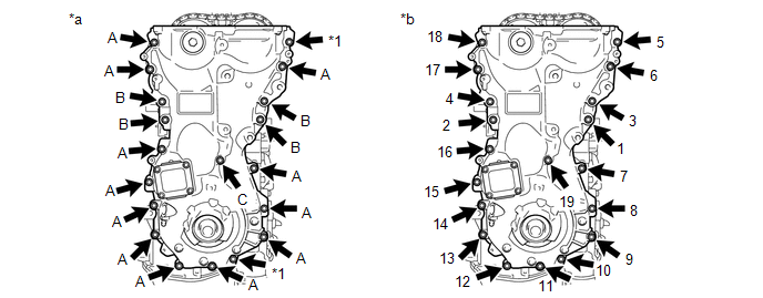
| *1 | Nut | - | - |
| *a | Types of nut and bolt | *b | Tightening Order |
Bolt Length:
| Item | Length | Thread Diameter |
|---|---|---|
| Bolt A | 30 mm (1.18 in.) | 8 mm (0.315 in.) |
| Bolt B | 35 mm (1.38 in.) | 10 mm (0.394 in.) |
| Bolt C | 45 mm (1.77 in.) | 8 mm (0.315 in.) |
NOTICE:
Do not apply oil to bolts. Clean off if any oil is applied to bolts.
(f) Tighten the 17 bolts and 2 nuts in several steps, in the sequence shown in the illustration.
Torque:
Bolts A, C and nut :
21 N·m {214 kgf·cm, 15 ft·lbf}
Bolt B :
55 N·m {561 kgf·cm, 41 ft·lbf}
2. INSTALL ENGINE MOUNTING BRACKET RH
Click here .gif)
3. INSTALL TIMING CHAIN COVER OIL SEAL
Click here
4. INSTALL V-RIBBED BELT TENSIONER ASSEMBLY
Click here
5. INSTALL CRANKSHAFT PULLEY ASSEMBLY
Click here
6. INSTALL CRANKSHAFT POSITION SENSOR
Click here
7. INSTALL CYLINDER HEAD COVER SUB-ASSEMBLY
Click here
8. INSTALL IGNITION COIL ASSEMBLY
Click here
9. INSTALL ENGINE WIRE
Click here
10. INSTALL ENGINE AND TRANSAXLE
Click here
READ NEXT:
 Power Switch
ComponentsCOMPONENTS ILLUSTRATION *1 INSTRUMENT CLUSTER FINISH PANEL SUB-ASSEMBLY *2 POWER SWITCH RemovalREMOVAL PROCEDURE 1. REMOVE INSTRUMENT CLUSTER FINISH PANEL SUB-ASSEMBLY Click h
SEE MORE:
Front Camera Feedback Malfunction (C1681)
DESCRIPTION This DTC is stored if the parking assist ECU judges as a result of its self check that a synchronization problem is occurring in the image signal sent from the front television camera assembly to the parking assist ECU. DTC No. Detection Item DTC Detection Condition Trouble Area
IG Power Supply Voltage (C1551)
DESCRIPTION The power steering ECU assembly distinguishes the power switch status as on (IG) or off through the IG power source circuit. DTC No. Detection Item DTC Detection Condition Trouble Area Warning Indicate Return-to-normal Condition C1551 IG Power Supply Voltage IG power
