Lexus NX: Components
COMPONENTS
ILLUSTRATION
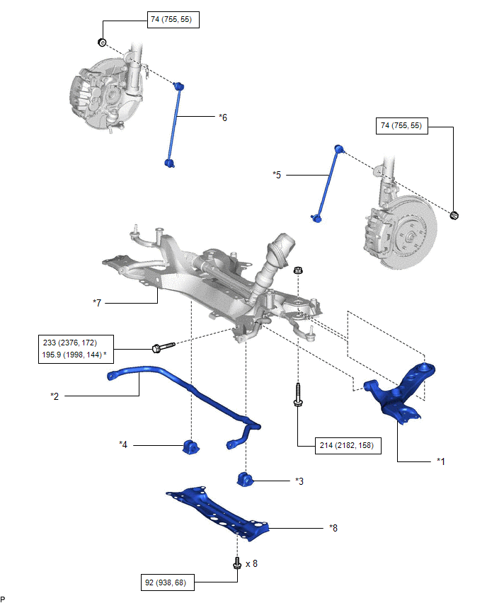
| *1 | FRONT LOWER NO. 1 SUSPENSION ARM SUB-ASSEMBLY LH | *2 | FRONT STABILIZER BAR |
| *3 | FRONT STABILIZER BAR BUSHING LH | *4 | FRONT STABILIZER BAR BUSHING RH |
| *5 | FRONT STABILIZER LINK ASSEMBLY LH | *6 | FRONT STABILIZER LINK ASSEMBLY RH |
| *7 | FRONT SUSPENSION CROSSMEMBER SUB-ASSEMBLY | *8 | FRONT SUSPENSION MEMBER BRACE |
.png) | N*m (kgf*cm, ft.*lbf): Specified torque | * | For use with SST |
READ NEXT:
 Removal
REMOVAL PROCEDURE 1. REMOVE FRONT SUSPENSION CROSSMEMBER SUB-ASSEMBLY Click here 2. REMOVE FRONT STABILIZER LINK ASSEMBLY LH (a) Remove the nut and front stabilizer link assembly LH. HINT: If the
Inspection
INSPECTION PROCEDURE 1. INSPECT FRONT STABILIZER LINK ASSEMBLY LH (a) Inspect the turning torque of the ball joint. (1) Secure the front stabilizer link assembly in a vise using aluminum plates. (2
Installation
INSTALLATION PROCEDURE 1. INSTALL FRONT STABILIZER BAR BUSHING LH *1 Stopper Front of the Vehicle (a) Install the front stabilizer bar bushing to the front stabilizer bar as shown in t
SEE MORE:
Window Glass Antenna Wire
On-vehicle InspectionON-VEHICLE INSPECTION PROCEDURE 1. INSPECT WINDOW GLASS ANTENNA WIRE (a) Check for continuity of the antenna. HINT: Check for continuity at the center of each antenna wire as shown in the illustration. NOTICE:
When cleaning the quarter window assembly, wipe it in the di
Headlight ECU Communication Stop Mode
DESCRIPTION Detection Item Symptom Trouble Area Headlight ECU Communication Stop Mode Any of the following conditions are met:
Communication stop for "Headlight swivel (AFS)" is indicated on the "Communication Bus Check" screen of the Techstream.
Click here
Communication system
© 2016-2026 Copyright www.lexunx.com
