Lexus NX: Components
COMPONENTS
ILLUSTRATION
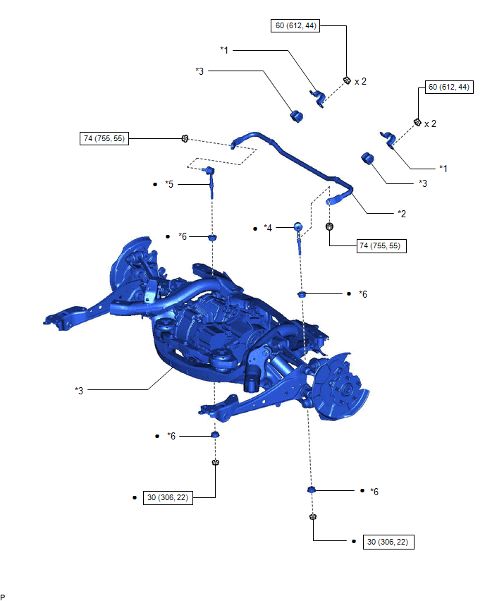
| *1 | REAR NO. 1 STABILIZER BAR BRACKET | *2 | REAR STABILIZER BAR |
| *3 | REAR STABILIZER BUSHING | *4 | REAR STABILIZER LINK ASSEMBLY LH |
| *5 | REAR STABILIZER LINK ASSEMBLY RH | *6 | REAR STABILIZER CUSHION |
.png) | N*m (kgf*cm, ft.*lbf): Specified torque | ● | Non-reusable part |
READ NEXT:
 Removal
REMOVAL PROCEDURE 1. REMOVE REAR STABILIZER LINK ASSEMBLY LH (a) Remove the 2 nuts and 2 cushions and disconnect the rear stabilizer link assembly LH from the rear No. 2 suspension arm assembly LH.
Inspection
INSPECTION CAUTION / NOTICE / HINT HINT:
Use the same procedure for the RH and LH sides.
The procedure listed below is for the LH side.
PROCEDURE 1. INSPECT REAR STABILIZER LINK ASSEMBLY LH N
Installation
INSTALLATION PROCEDURE 1. INSTALL REAR STABILIZER BUSHING (a) Install the 2 rear stabilizer bushings to the rear stabilizer bar on the outside of the bush stoppers as shown in the illustration. NOTIC
SEE MORE:
Parts Location
PARTS LOCATION ILLUSTRATION *1 REAR HEIGHT CONTROL SENSOR SUB-ASSEMBLY LH *2 BRAKE BOOSTER WITH MASTER CYLINDER ASSEMBLY (SKID CONTROL ECU) *3 HEADLIGHT ASSEMBLY LH - HEADLIGHT ECU SUB-ASSEMBLY LH - HEADLIGHT UNIT ASSEMBLY LH *4 HEADLIGHT ASSEMBLY RH - HEADLIGHT ECU SUB-ASSEMBLY
Sub Radiator
RemovalREMOVAL PROCEDURE 1. REMOVE NO. 1 ENGINE UNDER COVER ASSEMBLY Click here 2. DRAIN COOLANT (for Inverter Coolant) Click here 3. REMOVE UPPER RADIATOR SUPPORT SUB-ASSEMBLY Click here 4. REMOVE NO. 2 FAN SHROUD Click here 5. REMOVE RADIATOR ASSEMBLY (for Inverter Coolant) (a) Slide
© 2016-2026 Copyright www.lexunx.com
