Lexus NX: Installation
INSTALLATION
PROCEDURE
1. INSTALL CABLE SUPPORT BRACKET
(a) Install the cable support bracket to the rear suspension member sub-assembly with the 2 bolts.
Torque:
6.0 N·m {61 kgf·cm, 53 in·lbf}
2. INSTALL REAR STABILIZER SUPPORT BRACKET LH
(a) Install the rear stabilizer support bracket LH to the rear suspension member sub-assembly with the 4 bolts.
Torque:
50 N·m {510 kgf·cm, 37 ft·lbf}
3. INSTALL REAR STABILIZER SUPPORT BRACKET RH
(a) Install the rear stabilizer support bracket RH to the rear suspension member sub-assembly with the 4 bolts.
Torque:
50 N·m {510 kgf·cm, 37 ft·lbf}
4. INSTALL REAR STABILIZER BUSHING
Click here .gif)
5. INSTALL REAR STABILIZER BAR
Click here
6. INSTALL REAR NO. 1 STABILIZER BAR BRACKET
Click here
7. INSTALL FRONT DIFFERENTIAL SUPPORT ASSEMBLY
Click here
8. INSTALL DIFFERENTIAL MOUNT CUSHION
Click here
9. INSTALL REAR TRACTION WITH TRANSAXLE MOTOR ASSEMBLY
Click here
10. INSTALL REAR SUSPENSION MEMBER SUB-ASSEMBLY
(a) Place wooden blocks or plate lift attachments on an engine lifter, and then set the rear suspension member sub-assembly so that the attachments are in the positions shown in the illustration.
.png)
| *a | Plate Lift Attachment |
| *b | Engine Lifter |
.png) | Attachment Placement Positions |
NOTICE:
- Place the wooden blocks or plate lift attachments so that the rear suspension member sub-assembly is level.
- As the rear suspension member sub-assembly is very heavy, be sure to support it securely.
(b) Install the rear suspension member and 2 rear upper body mounting cushions with the 2 bolts and 2 nuts.
Torque:
for bolt :
102 N·m {1040 kgf·cm, 75 ft·lbf}
for nut :
125 N·m {1275 kgf·cm, 92 ft·lbf}
11. CONNECT WIRE HARNESS
| (a) Attach the 3 clamps and connect the wire harness. |
|
.png)
12. INSTALL EXHAUST TAILPIPE ASSEMBLY
Click here
13. TEMPORARILY INSTALL REAR NO. 2 SUSPENSION ARM ASSEMBLY LH
Click here
14. TEMPORARILY INSTALL REAR NO. 2 SUSPENSION ARM ASSEMBLY RH
HINT:
Use the same procedure described for the LH side.
15. TEMPORARILY INSTALL REAR NO. 1 SUSPENSION ARM ASSEMBLY LH
Click here
16. TEMPORARILY INSTALL REAR NO. 1 SUSPENSION ARM ASSEMBLY RH
HINT:
Use the same procedure described for the LH side.
17. TEMPORARILY INSTALL REAR UPPER CONTROL ARM ASSEMBLY LH
Click here
18. TEMPORARILY INSTALL REAR UPPER CONTROL ARM ASSEMBLY RH
HINT:
Use the same procedure described for the LH side.
19. TEMPORARILY INSTALL REAR SHOCK ABSORBER ASSEMBLY LH
Click here
20. TEMPORARILY INSTALL REAR SHOCK ABSORBER ASSEMBLY RH
HINT:
Use the same procedure described for the LH side.
21. INSTALL REAR AXLE CARRIER SUB-ASSEMBLY LH
Click here
22. INSTALL REAR AXLE CARRIER SUB-ASSEMBLY RH
HINT:
Use the same procedure described for the LH side.
23. TEMPORARILY INSTALL REAR NO. 2 SUSPENSION ARM ASSEMBLY LH
Click here
24. TEMPORARILY INSTALL REAR NO. 2 SUSPENSION ARM ASSEMBLY RH
HINT:
Use the same procedure described for the LH side.
25. INSTALL REAR TRAILING ARM ASSEMBLY LH
Click here
26. INSTALL REAR TRAILING ARM ASSEMBLY RH
HINT:
Use the same procedure described for the LH side.
27. TEMPORARILY INSTALL REAR NO. 1 SUSPENSION ARM ASSEMBLY LH
Click here
28. TEMPORARILY INSTALL REAR NO. 1 SUSPENSION ARM ASSEMBLY RH
HINT:
Use the same procedure described for the LH side.
29. CONNECT REAR NO. 1 SHOCK ABSORBER BRACKET LH
Click here
30. CONNECT REAR NO. 1 SHOCK ABSORBER BRACKET RH
HINT:
Use the same procedure described for the LH side.
31. INSTALL REAR HEIGHT CONTROL SENSOR SUB-ASSEMBLY LH
Click here
32. STABILIZE SUSPENSION
Click here
33. TIGHTEN REAR UPPER CONTROL ARM ASSEMBLY LH
Click here
34. TIGHTEN REAR UPPER CONTROL ARM ASSEMBLY RH
HINT:
Use the same procedure described for the LH side.
35. TIGHTEN REAR NO. 2 SUSPENSION ARM ASSEMBLY LH
Click here
36. TIGHTEN REAR NO. 2 SUSPENSION ARM ASSEMBLY RH
HINT:
Use the same procedure described for the LH side.
37. TIGHTEN REAR NO. 1 SUSPENSION ARM ASSEMBLY LH
Click here
38. TIGHTEN REAR NO. 1 SUSPENSION ARM ASSEMBLY RH
HINT:
Use the same procedure described for the LH side.
39. TIGHTEN REAR SHOCK ABSORBER ASSEMBLY LH
Click here
40. TIGHTEN REAR SHOCK ABSORBER ASSEMBLY RH
HINT:
Use the same procedure described for the LH side.
41. CONNECT PARKING BRAKE WIRE ASSEMBLY NO.1
Click here
42. INSTALL REAR SUSPENSION BRACE SUB-ASSEMBLY
(a) Install the rear suspension brace sub-assembly to the rear suspension member with the 6 bolts.
Torque:
35 N·m {357 kgf·cm, 26 ft·lbf}
43. INSTALL REAR STABILIZER LINK ASSEMBLY LH
Click here
44. INSTALL REAR STABILIZER LINK ASSEMBLY RH
HINT:
Use the same procedure described for the LH side.
45. INSTALL REAR AXLE HUB AND BEARING ASSEMBLY LH
Click here
46. INSTALL REAR AXLE HUB AND BEARING ASSEMBLY RH
HINT:
Use the same procedure described for the LH side.
47. INSTALL REAR DISC
Click here
48. CONNECT REAR DISC BRAKE CALIPER ASSEMBLY LH
Click here
49. CONNECT REAR DISC BRAKE CALIPER ASSEMBLY RH
HINT:
Use the same procedure described for the LH side.
50. INSTALL REAR AXLE SHAFT NUT LH
Click here
51. INSTALL REAR AXLE SHAFT NUT RH
HINT:
Use the same procedure described for the LH side.
52. INSPECT REAR AXLE HUB BEARING LOOSENESS
Click here
53. INSPECT REAR AXLE HUB RUNOUT
Click here
54. STAKE REAR AXLE SHAFT NUT LH
Click here
55. STAKE REAR AXLE SHAFT NUT RH
HINT:
Use the same procedure described for the LH side.
56. CONNECT REAR SPEED SENSOR LH
(a) w/ AVS:
Click here
(b) w/o AVS:
Click here
57. CONNECT REAR SPEED SENSOR RH
HINT:
Use the same procedure described for the LH side.
58. INSTALL REAR SUSPENSION ARM COVER LH
Click here
59. INSTALL REAR SUSPENSION ARM COVER RH
HINT:
Use the same procedure described for the LH side.
60. CONNECT WIRE HARNESS
Click here
61. INSTALL SERVICE PLUG GRIP
CAUTION:
Wear insulating gloves.
NOTICE:
Before connecting the service plug, check that no parts and tools remain and that the high voltage terminals and connectors are connected securely.
(a) Wear insulated gloves and install the service plug grip in the order shown in the illustration.
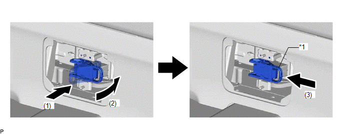
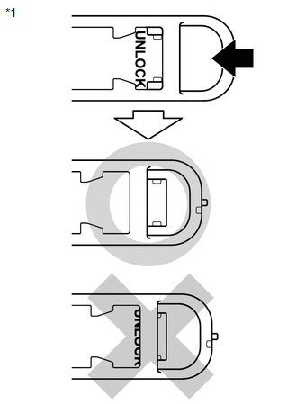
| *1 | Service Plug Grip Lever | - | - |
(1) Insert the service plug grip straight.
(2) Push down the lever 90°.
| (3) Slide the lever until it clicks to indicate that it is locked. NOTICE: Slide firmly to the left until the UNLOCK indication is hidden. |
|
(b) Rotate the handle of the service plug grip 90° toward the battery and slide it in the direction shown by the arrow until a click sound is heard.
62. INSTALL HYBRID BATTERY SERVICE PLUG COVER
CAUTION:
Wear insulated gloves and use insulated tools.
| (a) Using an insulated tool, install the hybrid battery service plug cover with the 2 nuts. |
|
.png)
63. INSTALL BATTERY SERVICE HOLE COVER
.png)
(a) Engage the 4 claws and install the battery service hole cover.
64. CONNECT CABLE TO NEGATIVE AUXILIARY BATTERY TERMINAL
(a) Connect the cable to the negative (-) auxiliary battery terminal and tighten the nut.
Torque:
5.4 N·m {55 kgf·cm, 48 in·lbf}
65. INITIALIZATION AFTER RECONNECTING AUXILIARY BATTERY TERMINAL
Click here
HINT:
When disconnecting and reconnecting the auxiliary battery, there is an automatic learning function that completes learning when the respective system is used.
Click here
66. INSTALL DECK FLOOR BOX LH
Click here
67. INSTALL REAR DECK FLOOR BOX
Click here
68. INSTALL NO. 3 DECK BOARD SUB-ASSEMBLY
Click here
69. INSTALL REAR WHEEL
Click here
70. INSPECT AND ADJUST REAR WHEEL ALIGNMENT
Click here
71. CHECK FOR SPEED SENSOR SIGNAL
Click here
72. HEIGHT CONTROL SENSOR SIGNAL INITIALIZATION
Click here
73. PERFORM INITIALIZATION
Click here
READ NEXT:
 Problem Symptoms Table
PROBLEM SYMPTOMS TABLE HINT: Use the table below to help determine the cause of problem symptoms. If multiple suspected areas are listed, the potential causes of the symptoms are listed in order of pr
SEE MORE:
Components
COMPONENTS ILLUSTRATION -
*A w/ Damper - - *1 SUSPENSION TOWER DAMPER - - N*m (kgf*cm, ft.*lbf): Specified torque - - ILLUSTRATION w/ Damper
*A w/o Damper - - *1 SUSPENSION TOWER DAMPER - - N*m (kgf*cm, ft.*lbf): Specified torque - -
Components
COMPONENTS ILLUSTRATION *1 COLUMN HOLE COVER SILENCER SHEET *2 COMBINATION SWITCH ASSEMBLY WITH SPIRAL CABLE SUB-ASSEMBLY *3 ELECTRIC POWER STEERING COLUMN SUB-ASSEMBLY *4 LOWER STEERING COLUMN COVER *5 NO. 1 AIR DUCT *6 NO. 2 STEERING INTERMEDIATE SHAFT ASSEMBLY *7
