Lexus NX: Components
COMPONENTS
ILLUSTRATION
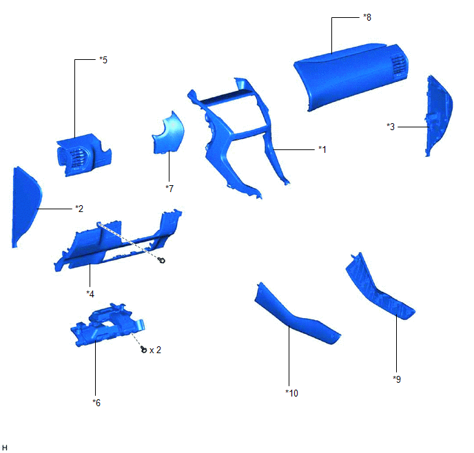
| *1 | CENTER INSTRUMENT CLUSTER FINISH PANEL ASSEMBLY | *2 | INSTRUMENT SIDE PANEL LH |
| *3 | INSTRUMENT SIDE PANEL RH | *4 | LOWER NO. 1 INSTRUMENT PANEL FINISH PANEL |
| *5 | NO. 1 INSTRUMENT PANEL SAFETY PAD SUB-ASSEMBLY | *6 | NO. 1 INSTRUMENT PANEL UNDER COVER SUB-ASSEMBLY |
| *7 | NO. 1 SWITCH HOLE BASE | *8 | NO. 2 INSTRUMENT PANEL SAFETY PAD SUB-ASSEMBLY |
| *9 | UPPER NO. 1 CONSOLE PANEL GARNISH | *10 | UPPER NO. 2 CONSOLE PANEL GARNISH |
ILLUSTRATION
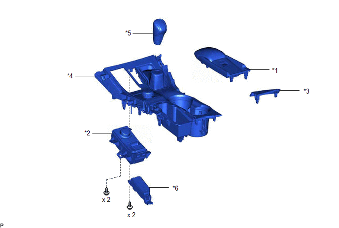
| *1 | CONSOLE ARMREST ASSEMBLY | *2 | INTEGRATION CONTROL AND PANEL ASSEMBLY (ABSORBER CONTROL SWITCH) |
| *3 | UPPER REAR CONSOLE PANEL | *4 | UPPER REAR CONSOLE PANEL SUB-ASSEMBLY |
| *5 | SHIFT LEVER KNOB SUB-ASSEMBLY | *6 | SHIFT POSITION INDICATOR |
READ NEXT:
 Removal
REMOVAL PROCEDURE 1. REMOVE CONSOLE ARMREST ASSEMBLY Click here 2. REMOVE UPPER REAR CONSOLE PANEL Click here 3. REMOVE UPPER NO. 2 CONSOLE PANEL GARNISH Click here 4. REMOVE UPPER NO. 1 CONSOLE
Inspection
INSPECTION PROCEDURE 1. INSPECT INTEGRATION CONTROL AND PANEL ASSEMBLY (ABSORBER CONTROL SWITCH) (a) Measure the resistance according to the value(s) in the table below. Standard Resistance: Te
Installation
INSTALLATION PROCEDURE 1. INSTALL INTEGRATION CONTROL AND PANEL ASSEMBLY (ABSORBER CONTROL SWITCH) (a) Install the integration control and panel assembly (absorber control switch) to the upper rear
SEE MORE:
Installation
INSTALLATION CAUTION / NOTICE / HINT HINT:
Use the same procedure for the RH and LH sides.
The following procedure is for the LH side.
NOTICE: When the brake pedal is first depressed after replacing the brake pads or pushing back the disc brake piston, DTC C1214 may be output. As there is no
Fail-safe Chart
FAIL-SAFE CHART FAIL-SAFE FUNCTION (w/ Rain Sensor) (a) When the windshield wiper switch assembly is in the AUTO position and any of the following conditions are met, intermittent operation according to the sensitivity setting is performed. (1) Rain sensor output malfunction (b) When the windshield
© 2016-2026 Copyright www.lexunx.com
