Lexus NX: Reassembly
REASSEMBLY
CAUTION / NOTICE / HINT
HINT:
- Use the same procedure for the RH and LH sides.
- The procedure listed below is for the LH side.
PROCEDURE
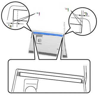
1. INSTALL NO. 3 MOULDING TAPE
(a) Clean the No. 3 moulding tape installation surface.
(1) When reusing the side mudguard LH, remove the double-sided tape remaining on the No. 3 moulding tape installation surface.
NOTICE:
- Installing the No. 3 moulding tape with some double-sided tape remaining may cause poor adhesion.
- Removing with a screwdriver, etc. may cause damage or poor adhesion.
(2) Clean the No. 3 moulding tape installation surface with a non-residue solvent.
(3) Apply primer to the No. 3 moulding tape installation area on the side mudguard LH.
NOTICE:
Do not apply too much primer.
(b) Remove the peeling paper on a new No. 3 moulding tape while making sure not to touch the adhesional surface.
| (c) Install a new No. 3 moulding tape in the position shown in the illustration. NOTICE:
|
|
READ NEXT:
 Installation
INSTALLATION CAUTION / NOTICE / HINT HINT:
Use the same procedure for the RH and LH sides.
The procedure listed below is for the LH side.
PROCEDURE 1. INSTALL SIDE MUDGUARD SUB-ASSEMBLY LH HIN
Components
COMPONENTS ILLUSTRATION *1 FRONT FENDER MOULDING SUB-ASSEMBLY LH - - ILLUSTRATION *1 NO. 1 MOULDING TAPE *2 NO. 2 MOULDING TAPE ● Non-reusable part - -
SEE MORE:
Stop Switch Circuit Malfunction (C164E)
DESCRIPTION When a stop light switch assembly circuit malfunction signal sent from the electronically controlled brake system is detected by the clearance warning ECU assembly, DTC C164E is stored. DTC No. Detection Item DTC Detection Condition Trouble Area C164E Stop Switch Circuit M
Removal
REMOVAL PROCEDURE 1. PRECAUTION Click here 2. REMOVE SERVICE PLUG GRIP Click here 3. DRAIN COOLANT (for Inverter Coolant) Click here 4. DISCONNECT WIRE HARNESS (a) Disconnect the 4 wire harness clamps from the inverter reserve tank assembly and inverter with converter assembly.
© 2016-2026 Copyright www.lexunx.com
