Lexus NX: Removal
REMOVAL
PROCEDURE
1. REMOVE CONSOLE ARMREST ASSEMBLY
Click here .gif)
2. REMOVE UPPER REAR CONSOLE PANEL
Click here
3. REMOVE UPPER NO. 2 CONSOLE PANEL GARNISH
Click here
4. REMOVE UPPER NO. 1 CONSOLE PANEL GARNISH
Click here
5. REMOVE INSTRUMENT SIDE PANEL LH
Click here
6. REMOVE NO. 1 INSTRUMENT PANEL SAFETY PAD SUB-ASSEMBLY
Click here
7. REMOVE NO. 1 INSTRUMENT PANEL UNDER COVER SUB-ASSEMBLY
Click here
8. REMOVE LOWER NO. 1 INSTRUMENT PANEL FINISH PANEL
Click here
9. REMOVE NO. 1 SWITCH HOLE BASE
Click here
10. REMOVE INSTRUMENT SIDE PANEL RH
Click here
11. REMOVE NO. 2 INSTRUMENT PANEL SAFETY PAD SUB-ASSEMBLY
Click here
12. REMOVE CENTER INSTRUMENT CLUSTER FINISH PANEL ASSEMBLY
Click here
13. REMOVE SHIFT LEVER KNOB SUB-ASSEMBLY
Click here
14. REMOVE UPPER REAR CONSOLE PANEL SUB-ASSEMBLY
Click here
15. REMOVE SHIFT POSITION INDICATOR
Click here
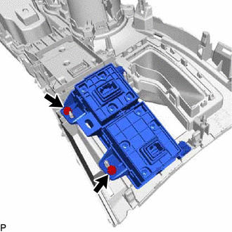
16. REMOVE INTEGRATION CONTROL AND PANEL ASSEMBLY (ABSORBER CONTROL SWITCH)
| (a) Remove the 2 screws and integration control and panel assembly (absorber control switch) from the upper rear console panel sub-assembly. |
|
READ NEXT:
 Inspection
INSPECTION PROCEDURE 1. INSPECT INTEGRATION CONTROL AND PANEL ASSEMBLY (ABSORBER CONTROL SWITCH) (a) Measure the resistance according to the value(s) in the table below. Standard Resistance: Te
Installation
INSTALLATION PROCEDURE 1. INSTALL INTEGRATION CONTROL AND PANEL ASSEMBLY (ABSORBER CONTROL SWITCH) (a) Install the integration control and panel assembly (absorber control switch) to the upper rear
SEE MORE:
Installation
INSTALLATION CAUTION / NOTICE / HINT HINT:
Use the same procedure for the RH and LH sides.
The procedure described below is for the LH side.
PROCEDURE 1. INSTALL REAR LIGHT ASSEMBLY LH (a) Attach the guide, clip and pin to set the rear light assembly LH. *a Pin *b Gui
Terminals Of Ecu
TERMINALS OF ECU MOBILE WIRELESS CHARGER CRADLE ASSEMBLY Terminal No. (Symbol) Wiring Color Terminal Description Condition Specified Condition
*1: When the power switch is turned from off to on (ACC), the mobile wireless charger cradle assembly checks the charging stop signal for 1 s
