Lexus NX: Components
COMPONENTS
ILLUSTRATION
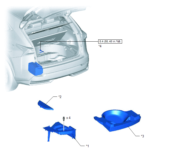
| *1 | DECK FLOOR BOX LH | *2 | NO. 3 DECK BOARD SUB-ASSEMBLY |
| *3 | REAR DECK FLOOR BOX | *4 | NEGATIVE AUXILIARY BATTERY TERMINAL |
.png) | N*m (kgf*cm, ft.*lbf): Specified torque | - | - |
ILLUSTRATION
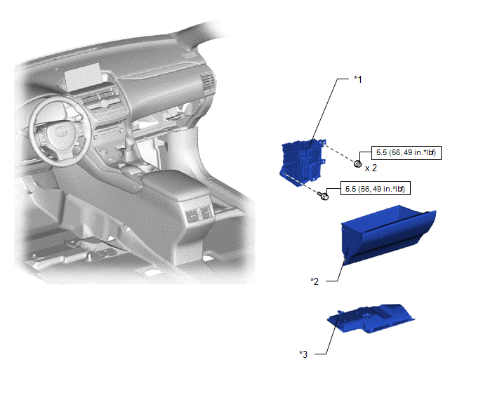
| *1 | ECU INTEGRATION BOX RH | *2 | GLOVE COMPARTMENT DOOR ASSEMBLY |
| *3 | NO. 2 INSTRUMENT PANEL UNDER COVER SUB-ASSEMBLY | - | - |
| | N*m (kgf*cm, ft.*lbf): Specified torque | - | - |
ILLUSTRATION
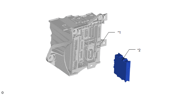
| *1 | ECU INTEGRATION BOX RH | *2 | TIRE PRESSURE MONITOR INITIATOR DRIVER |
READ NEXT:
 Removal
REMOVAL PROCEDURE 1. PRECAUTION NOTICE: After turning the power switch off, there may be a waiting time before disconnecting the negative (-) auxiliary battery terminal. Click here 2. REMOVE NO. 3 D
Installation
INSTALLATION PROCEDURE 1. INSTALL TIRE PRESSURE MONITOR INITIATOR DRIVER (a) Attach the 2 claws to install the tire pressure monitor initiator driver. 2. INSTALL ECU INTEGRATION BOX RH (a) Install the
SEE MORE:
Data List / Active Test
DATA LIST / ACTIVE TEST DATA LIST HINT: Using the Techstream to read the Data List allows the values or states of switches, sensors, actuators and other items to be read without removing any parts. This non-intrusive inspection can be very useful because intermittent conditions or signals may be dis
Inspection
INSPECTION PROCEDURE 1. INSPECT AIR CONDITIONING CONTROL ASSEMBLY (SEAT BELT WARNING LIGHT) (for Rear Side) (a) Check the seat belt warning light illumination. OK: Measurement Condition Specified Condition Battery positive (+) → Terminal 8 (IG+) Battery negative (-) → 1 (RRID) RH
© 2016-2026 Copyright www.lexunx.com
