Lexus NX: Removal
REMOVAL
PROCEDURE
1. PRECAUTION
NOTICE:
After turning the power switch off, there may be a waiting time before disconnecting the negative (-) auxiliary battery terminal.
Click here .gif)
2. REMOVE NO. 3 DECK BOARD SUB-ASSEMBLY
Click here
3. REMOVE REAR DECK FLOOR BOX
Click here
4. REMOVE DECK FLOOR BOX LH
Click here
5. DISCONNECT CABLE FROM NEGATIVE AUXILIARY BATTERY TERMINAL
6. REMOVE NO. 2 INSTRUMENT PANEL UNDER COVER SUB-ASSEMBLY
Click here
7. REMOVE GLOVE COMPARTMENT DOOR ASSEMBLY
Click here
8. REMOVE ECU INTEGRATION BOX RH
| (a) Disconnect the connectors. |
|
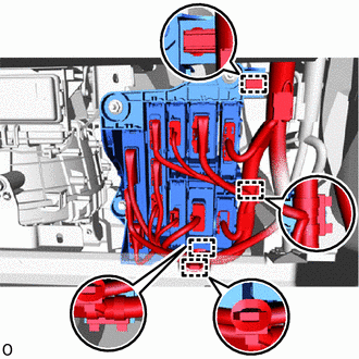
(b) Detach the 4 clamps.
(c) Remove the 2 nuts, bolt and ECU integration box RH.
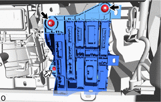
.png) | Nut |
.png) | Bolt |
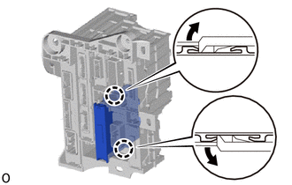
9. REMOVE TIRE PRESSURE MONITOR INITIATOR DRIVER
| (a) Detach the 2 claws and remove the tire pressure monitor initiator driver. |
|
READ NEXT:
 Installation
INSTALLATION PROCEDURE 1. INSTALL TIRE PRESSURE MONITOR INITIATOR DRIVER (a) Attach the 2 claws to install the tire pressure monitor initiator driver. 2. INSTALL ECU INTEGRATION BOX RH (a) Install the
Components
COMPONENTS ILLUSTRATION *1 DECK FLOOR BOX LH *2 NO. 3 DECK BOARD SUB-ASSEMBLY *3 REAR DECK FLOOR BOX *4 NEGATIVE AUXILIARY BATTERY TERMINAL N*m (kgf*cm, ft.*lbf): Specified
SEE MORE:
Installation
INSTALLATION PROCEDURE 1. INSTALL KICK DOOR CONTROL SENSOR (a) Insert the guide, attach the 2 claws and install the kick door control sensor to the kick door control bracket as shown in the illustration. NOTICE:
Do not subject the kick door control sensor to strong impacts or force, and do n
Precaution
PRECAUTION CAN COMMUNICATION SYSTEM TROUBLESHOOTING (a) Because the order of diagnosis is important to allow correct diagnosis, make sure to begin troubleshooting using How to Proceed with Troubleshooting when CAN communication system related DTCs are output. Click here (b) Precaution for steerin
