Lexus NX: Automatic High Beam System does not Operate or Operation Indicator does not Illuminate
DESCRIPTION
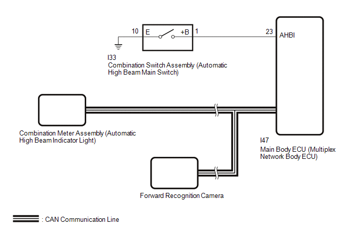
The main body ECU (multiplex network body ECU) controls the automatic high beam system based on signals received from the forward recognition camera.
WIRING DIAGRAM
CAUTION / NOTICE / HINT
NOTICE:
-
Before replacing the main body ECU (multiplex network body ECU), refer to Registration.
Click here
.gif)
- When replacing the forward recognition camera, always replace it with a new one. If a forward recognition camera which was installed to another vehicle is used, the information stored in the forward recognition camera will not match the information from the vehicle. As a result, a DTC may be stored.
-
If the forward recognition camera has been replaced with a new one, be sure to perform Forward Recognition Camera Learning.
for sequential recognition: Click here
for one time recognition: Click here
- Before performing troubleshooting, check that the low beam headlights and high beam headlights illuminate correctly.
- When replacing the combination meter assembly, always replace it with a new one. If a combination meter assembly which was installed to another vehicle is used, the information stored in it will not match the information from the vehicle and a DTC may be stored.
- If the forward recognition camera cannot operate due to high vehicle interior temperatures, bad weather (rain, fog, etc.) or fogged up or dirty glass, the automatic high beam system will not operate and the automatic high beam indicator will not illuminate.
-
Before performing troubleshooting, check that the front radar sensor system operates correctly.
Click here
PROCEDURE
| 1. | READ VALUE USING TECHSTREAM |
(a) Connect the Techstream to the DLC3.
(b) Turn the power switch on (IG).
(c) Turn the Techstream on.
(d) Enter the following menus: Chassis / Front Recognition Camera / Data List.
(e) Read the Data List according to the display on the Techstream.
Chassis > Front Recognition Camera > Data List| Tester Display | Measurement Item | Range | Normal Condition | Diagnostic Note |
|---|---|---|---|---|
| Front Recognition Camera High Temperature 2 | Whether high temperature malfunction of forward recognition camera exists or not | Not High Temperature or High Temperature | Not High Temperature: Approximately 65°C (149°F) or less High Temperature: Approximately 65°C (149°F) or higher | If this item is "High Temperature", the automatic high beam system will be temporarily unavailable. If this does not improve even if the inside of the vehicle is left cooled for at least 10 minutes, the forward recognition camera may be malfunctioning. HINT: In summertime, the windshield glass may reach 100°C (212°F) or higher |
| Tester Display |
|---|
| Front Recognition Camera High Temperature 2 |
OK:
"Not High Temperature" is displayed on the Techstream.
HINT:
If "High Temperature" is displayed, move the vehicle to a cool place and allow the temperature of the forward recognition camera to decrease before continuing with troubleshooting.
| NG | .gif) | END (TEMPORARY SUSPENSION OF AUTOMATIC HIGH BEAM SYSTEM DUE TO HIGH FORWARD RECOGNITION CAMERA TEMPERATURE) |
|
.gif)
| 2. | CHECK AUTOMATIC HIGH BEAM INDICATOR LIGHT |
(a) Check the operation of the automatic high beam indicator light.
- Turn the power switch on (IG).
- Turn the light control switch to the Auto or Head position.
- Turn the headlight dimmer switch to the low position.
- Turn the combination switch assembly (automatic high beam main switch) on.
OK:
Automatic high beam indicator light illuminates.
| NG | | GO TO STEP 5 |
|
| 3. | READ VALUE USING TECHSTREAM |
(a) Using the Techstream, read the Data List.
Click here
| (1) Shine a light on the automatic high beam sensor*. HINT: *: If troubleshooting is being performed in a bright area, such as outside on a sunny day, it will not be necessary to perform this step. Body Electrical > Main Body > Data List
OK: The Data List value displays "Daytime". |
|
| NG | | REPLACE FORWARD RECOGNITION CAMERA |
|
| 4. | READ VALUE USING TECHSTREAM |
(a) Using the Techstream, read the Data List.
Click here
| (1) Cover the automatic high beam sensor with an opaque object, such as cardboard. NOTICE:
OK: The Data List value displays "Speed". |
|
| OK | | USE SIMULATION METHOD TO CHECK |
| NG | | REPLACE FORWARD RECOGNITION CAMERA |
| 5. | READ VALUE USING TECHSTREAM |
(a) Using the Techstream, read the Data List.
Click here
| Tester Display | Measurement Item | Range | Normal Condition | Diagnostic Note |
|---|---|---|---|---|
| Auto High Beam Main Switch | Combination switch assembly (automatic high beam main switch) signal | OFF or ON | OFF: Combination switch assembly (automatic high beam main switch) off ON: Combination switch assembly (automatic high beam main switch) on | - |
| Tester Display |
|---|
| Auto High Beam Main Switch |
OK:
Normal condition listed above is displayed.
| NG | | GO TO STEP 8 |
|
| 6. | READ VALUE USING TECHSTREAM |
(a) Using the Techstream, read the Data List.
Click here
| Tester Display | Measurement Item | Range | Normal Condition | Diagnostic Note |
|---|---|---|---|---|
| Auto H Beam STS0 | Automatic high beam sensor state past 0 | Undetec, CAM NA, No sens, Hlight, Taillgt, Speed, Daytime, Village, Malfunc, Delay, Aim Lmt, SAE Mod, Undefin or LIN Err | Condition can be displayed | - |
| Tester Display |
|---|
| Auto H Beam STS0 |
OK:
The Data List value displays "Daytime" or "Speed".
| NG | | REPLACE FORWARD RECOGNITION CAMERA |
|
| 7. | PERFORM ACTIVE TEST USING TECHSTREAM |
(a) Perform the Active Test according to the display on the Techstream.
Click here
| Tester Display | Measurement Item | Control Range | Diagnostic Note |
|---|---|---|---|
| Automatic High Beam Indicator | Automatic high beam indicator light | OFF or ON | - |
| Tester Display |
|---|
| Automatic High Beam Indicator |
OK:
Automatic high beam indicator light illuminates.
| OK | | REPLACE MAIN BODY ECU (MULTIPLEX NETWORK BODY ECU) |
| NG | | REPLACE COMBINATION METER ASSEMBLY |
| 8. | INSPECT COMBINATION SWITCH ASSEMBLY (AUTOMATIC HIGH BEAM MAIN SWITCH) |
(a) Remove the combination switch assembly (automatic high beam main switch).
Click here
(b) Inspect the combination switch assembly (automatic high beam main switch).
Click here
| NG | | REPLACE COMBINATION SWITCH ASSEMBLY (AUTOMATIC HIGH BEAM MAIN SWITCH) |
|
| 9. | CHECK HARNESS AND CONNECTOR (COMBINATION SWITCH ASSEMBLY [AUTOMATIC HIGH BEAM MAIN SWITCH] - MAIN BODY ECU [MULTIPLEX NETWORK BODY ECU] AND BODY GROUND) |
(a) Disconnect the I33 combination switch assembly (automatic high beam main switch) connector.
(b) Disconnect the I47 main body ECU (multiplex network body ECU) connector.
(c) Measure the resistance according to the value(s) in the table below.
Standard Resistance:
| Tester Connection | Condition | Specified Condition |
|---|---|---|
| I33-1 (+B) - I47-23 (AHBI) | Always | Below 1 Ω |
| I33-10 (E) - Body ground | Always | Below 1 Ω |
| I33-1 (+B) or I47-23 (AHBI) - Body ground | Always | 10 kΩ or higher |
| OK | | REPLACE MAIN BODY ECU (MULTIPLEX NETWORK BODY ECU) |
| NG | | REPAIR OR REPLACE HARNESS OR CONNECTOR |
READ NEXT:
 Components
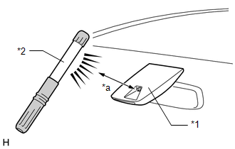
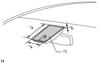
COMPONENTS ILLUSTRATION *1 AUTOMATIC LIGHT CONTROL SENSOR *2 NO. 1 SPEAKER OPENING COVER ASSEMBLY
Removal
REMOVAL PROCEDURE 1. REMOVE NO. 1 SPEAKER OPENING COVER ASSEMBLY Click here 2. REMOVE AUTOMATIC LIGHT CONTROL SENSOR (a) Detach the 2 claws and remove the automatic light control sensor.
SEE MORE:
Installation
INSTALLATION CAUTION / NOTICE / HINT HINT:
Use the same procedure for the RH and LH sides.
The procedure listed below is for the LH side.
PROCEDURE 1. INSTALL SST (a) Align the cutout on end of the shock rod of the front shock absorber assembly LH with the installation position. NOTICE: Be s
Data List / Active Test
DATA LIST / ACTIVE TEST DATA LIST HINT: Using the Techstream to read the Data List allows the values or states of switches, sensors, actuators and other items to be read without removing any parts. This non-intrusive inspection can be very useful because intermittent conditions or signals may be dis
