Lexus NX: Components
COMPONENTS
ILLUSTRATION
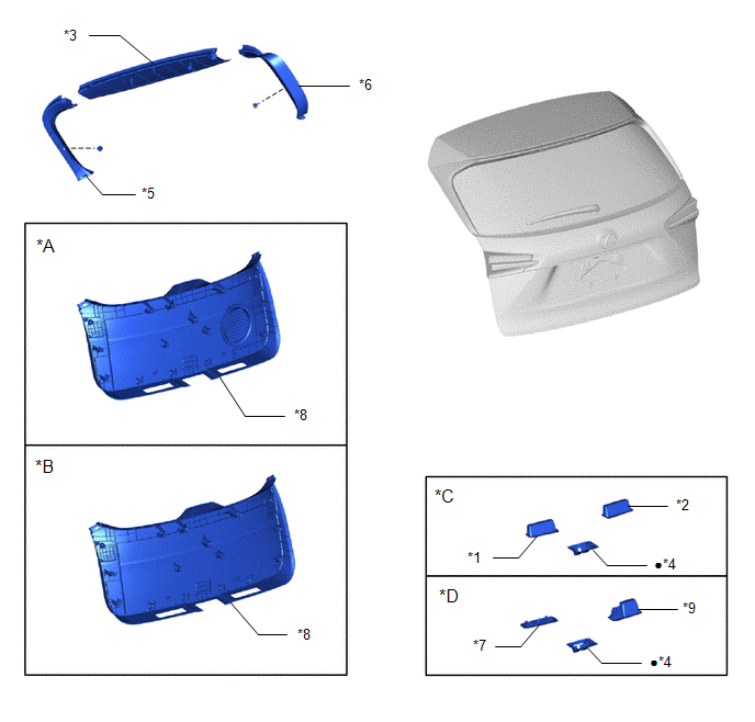
| *A | w/ Woofer | *B | w/o Woofer |
| *C | w/o Power Back Door | *D | w/ Power Back Door |
| *1 | BACK DOOR CENTER GARNISH | *2 | BACK DOOR FINISH COVER LH |
| *3 | BACK DOOR FINISH COVER RH | *4 | BACK DOOR LOCK COVER |
| *5 | BACK DOOR SIDE GARNISH LH | *6 | BACK DOOR SIDE GARNISH RH |
| *7 | BACK DOOR TRIM BASE | *8 | BACK DOOR TRIM BOARD ASSEMBLY |
| *9 | PULL HANDLE | - | - |
| ● | Non-reusable part | - | - |
ILLUSTRATION
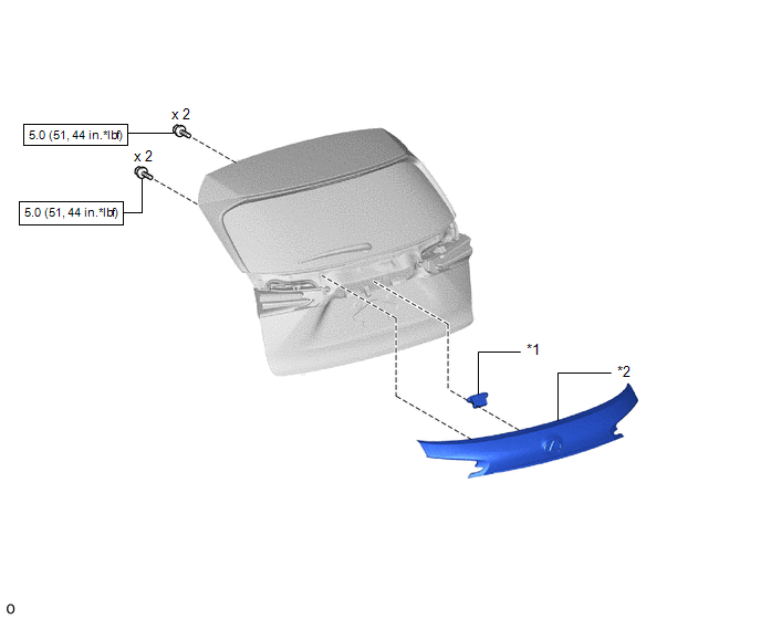
| *1 | BACK DOOR OPENER SWITCH ASSEMBLY | *2 | BACK DOOR OUTSIDE GARNISH SUB-ASSEMBLY |
.png) | N*m (kgf*cm, ft.*lbf): Specified torque | - | - |
READ NEXT:
 Removal
REMOVAL PROCEDURE 1. PRECAUTION Click here 2. REMOVE BACK DOOR CENTER GARNISH Click here 3. REMOVE BACK DOOR SIDE GARNISH LH Click here 4. REMOVE BACK DOOR SIDE GARNISH RH Click here 5. RE
Inspection
INSPECTION PROCEDURE 1. INSPECT BACK DOOR OPENER SWITCH ASSEMBLY (a) Check the operation of the opener switch. (1) Measure the resistance according to the value(s) in the table below. Standard Resi
Installation
INSTALLATION PROCEDURE 1. INSTALL BACK DOOR OPENER SWITCH ASSEMBLY (a) Connect the connector. (b) Install the back door opener switch assembly. 2. INSTALL BACK DOOR OUTSIDE GARNISH SUB-ASSEMBLY Click
SEE MORE:
Data List / Active Test
DATA LIST / ACTIVE TEST DATA LIST NOTICE: In the table below, the values listed under "Normal Condition" are reference values. Do not depend solely on these reference values when deciding whether a part is faulty or not. HINT: Using the Techstream to read the Data List allows the values or states of
Installation
INSTALLATION PROCEDURE 1. INSTALL REAR BUMPER SIDE SUPPORT LH (a) Attach the 2 claws to install the rear bumper side support LH. (b) Attach the clip. (c) Install the screw. 2. INSTALL REAR BUMPER SIDE SUPPORT RH HINT: Use the same procedure as for the LH side. 3. INSTALL REAR BUMPER S
© 2016-2026 Copyright www.lexunx.com
