Lexus NX: Removal
REMOVAL
PROCEDURE
1. PRECAUTION
Click here .gif)
2. REMOVE BACK DOOR CENTER GARNISH
Click here
3. REMOVE BACK DOOR SIDE GARNISH LH
Click here
4. REMOVE BACK DOOR SIDE GARNISH RH
Click here
5. REMOVE BACK DOOR TRIM BASE (w/ Power Back Door)
Click here
6. REMOVE PULL HANDLE (w/ Power Back Door)
Click here
7. REMOVE BACK DOOR FINISH COVER LH (w/o Power Back Door)
Click here
8. REMOVE BACK DOOR FINISH COVER RH (w/o Power Back Door)
Click here
9. REMOVE BACK DOOR LOCK COVER (w/ Power Back Door)
Click here
10. REMOVE BACK DOOR LOCK COVER (w/o Power Back Door)
Click here
11. REMOVE BACK DOOR TRIM BOARD ASSEMBLY
Click here
12. REMOVE BACK DOOR OUTSIDE GARNISH SUB-ASSEMBLY
Click here
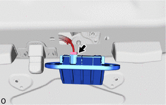
13. REMOVE BACK DOOR OPENER SWITCH ASSEMBLY
| (a) Disconnect the connector and remove the back door opener switch assembly. |
|
READ NEXT:
 Inspection
INSPECTION PROCEDURE 1. INSPECT BACK DOOR OPENER SWITCH ASSEMBLY (a) Check the operation of the opener switch. (1) Measure the resistance according to the value(s) in the table below. Standard Resi
Installation
INSTALLATION PROCEDURE 1. INSTALL BACK DOOR OPENER SWITCH ASSEMBLY (a) Connect the connector. (b) Install the back door opener switch assembly. 2. INSTALL BACK DOOR OUTSIDE GARNISH SUB-ASSEMBLY Click
Back Door Support
ComponentsCOMPONENTS ILLUSTRATION *1 BACK DOOR LOWER DAMPER STAY BRACKET LH *2 BACK DOOR STAY ASSEMBLY LH *3 BACK DOOR UPPER DAMPER STAY BRACKET LH - - N*m (kgf*cm, ft.*lbf
SEE MORE:
Problem Symptoms Table
PROBLEM SYMPTOMS TABLE HINT:
Use the table below to help determine the cause of problem symptoms. If multiple suspected areas are listed, the potential causes of the symptoms are listed in order of probability in the "Suspected Area" column of the table. Check each symptom by checking the suspect
Adjustment
ADJUSTMENT PROCEDURE 1. INSPECT AND ADJUST BRAKE PEDAL HEIGHT (a) Check the brake pedal height. *1 Brake Pedal Pad - - *a Brake Pedal Height *b Measuring Plane of Floor Panel Brake pedal height from floor panel: 188.9 to 198.9 mm (7.44 to 7.83 in.) (b) Adjust the brake pedal
