Lexus NX: Inspection
INSPECTION
PROCEDURE
1. INSPECT BACK DOOR OPENER SWITCH ASSEMBLY
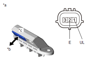
(a) Check the operation of the opener switch.
| (1) Measure the resistance according to the value(s) in the table below. Standard Resistance:
If the result is not as specified, replace the back door opener switch assembly. |
|
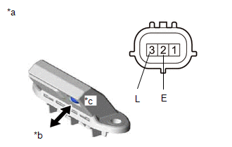
| (b) Check the operation of the lock switch. (1) Measure the resistance according to the value(s) in the table below. Standard Resistance:
If the result is not as specified, replace the back door opener switch assembly. |
|
READ NEXT:
 Installation
INSTALLATION PROCEDURE 1. INSTALL BACK DOOR OPENER SWITCH ASSEMBLY (a) Connect the connector. (b) Install the back door opener switch assembly. 2. INSTALL BACK DOOR OUTSIDE GARNISH SUB-ASSEMBLY Click
Back Door Support
ComponentsCOMPONENTS ILLUSTRATION *1 BACK DOOR LOWER DAMPER STAY BRACKET LH *2 BACK DOOR STAY ASSEMBLY LH *3 BACK DOOR UPPER DAMPER STAY BRACKET LH - - N*m (kgf*cm, ft.*lbf
Back Door Weatherstrip
ComponentsCOMPONENTS ILLUSTRATION *1 BACK DOOR WEATHERSTRIP - - ● Non-reusable part - - RemovalREMOVAL PROCEDURE 1. REMOVE BACK DOOR WEATHERSTRIP (a) Remove the back door
SEE MORE:
Driver Side Power Mirror cannot be Adjusted with Power Mirror Switch
DESCRIPTION When the outer mirror switch assembly mirror surface adjust switch (up/down/left/right) is operated, up/down/left/right signals are received by the main body ECU (multiplex network body ECU). The main body ECU (multiplex network body ECU) sends the received signals to the outer mirror co
Initialization
INITIALIZATION INITIALIZE (INITIAL POSITION MEMORIZATION) NOTICE: Perform initialization (initial position memorization) in the following situations.
When replacing the fold seat control ECU with a new one.
When canceling fold seat control ECU initialization (initial position reset).
HINT:
