Lexus NX: Removal
REMOVAL
CAUTION / NOTICE / HINT
HINT:
- Use the same procedure for the RH and LH sides.
- The procedure listed below is for the LH side.
PROCEDURE
1. PRECAUTION
NOTICE:
After the power switch off is turned off, there may be a waiting time before disconnecting the auxiliary negative (-) battery terminal.
Click here .gif)
2. REMOVE NO. 3 DECK BOARD SUB-ASSEMBLY
Click here
3. REMOVE REAR DECK FLOOR BOX
Click here
4. REMOVE DECK FLOOR BOX LH
Click here
5. DISCONNECT CABLE FROM NEGATIVE AUXILIARY BATTERY TERMINAL
NOTICE:
When disconnecting the cable, some systems need to be initialized after the cable is reconnected.
Click here
6. REMOVE REAR DOOR TRIM COVER LH
Click here
7. REMOVE REAR DOOR INSIDE HANDLE BEZEL PLUG LH
Click here
8. REMOVE REAR POWER WINDOW REGULATOR SWITCH ASSEMBLY WITH REAR DOOR ARMREST BASE PANEL
Click here
9. REMOVE REAR DOOR TRIM BOARD SUB-ASSEMBLY LH
Click here
10. REMOVE REAR DOOR INNER GLASS WEATHERSTRIP LH
Click here
11. REMOVE REAR DOOR ARMREST SET BRACKET LH
Click here
12. REMOVE REAR DOOR SERVICE HOLE COVER LH
Click here
13. REMOVE REAR DOOR GLASS RUN LH
Click here
14. REMOVE REAR DOOR REAR LOWER WINDOW FRAME SUB-ASSEMBLY LH
Click here
15. REMOVE REAR DOOR REAR GUIDE SEAL LH
Click here
16. REMOVE REAR DOOR GLASS SUB-ASSEMBLY LH
Click here
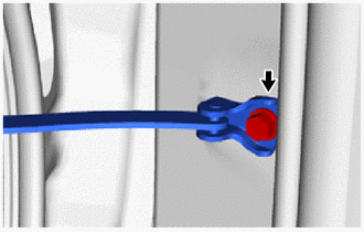
17. DISCONNECT REAR DOOR CHECK ASSEMBLY LH
| (a) Remove the bolt and disconnect the rear door check assembly LH. |
|
18. REMOVE REAR DOOR WEATHERSTRIP LH
Click here
19. REMOVE REAR DOOR FRAME GARNISH LH
Click here
20. REMOVE REAR DOOR BELT MOULDING ASSEMBLY LH
Click here
21. REMOVE REAR DOOR FRONT WINDOW FRAME MOULDING LH
Click here
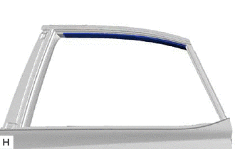
22. REMOVE REAR DOOR UPPER WINDOW FRAME MOULDING LH
Click here
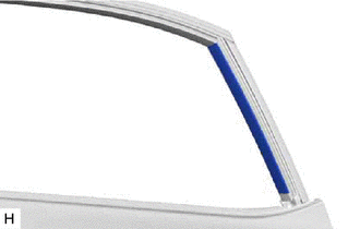
23. REMOVE REAR DOOR REAR WINDOW FRAME MOULDING LH
Click here
24. REMOVE NO. 1 BLACK OUT TAPE LH
HINT:
When removing the No. 1 black out tape LH, heat the rear door panel and No. 1 black out tape LH using a heat light.
Standard:
| Item | Temperature |
|---|---|
| Rear Door Panel | 40 to 60°C (104 to 140°F) |
| No. 1 Black Out Tape LH | 20 to 30°C (68 to 86°F) |
NOTICE:
Do not heat the rear door panel or No. 1 black out tape LH excessively.
| (a) Pull back an edge of the No. 1 black out tape LH and pull it parallel to the rear door panel to remove it. |
|
.png)
25. REMOVE NO. 2 BLACK OUT TAPE LH
HINT:
When removing the No. 2 black out tape LH, heat the rear door panel and No. 2 black out tape LH using a heat light.
Standard:
| Item | Temperature |
|---|---|
| Rear Door Panel | 40 to 60°C (104 to 140°F) |
| No. 2 Black Out Tape LH | 20 to 30°C (68 to 86°F) |
NOTICE:
Do not heat the rear door panel or No. 2 black out tape LH excessively.
| (a) Pull back an edge of the No. 2 black out tape LH and pull it parallel to the rear door panel to remove it. |
|
26. REMOVE NO. 3 BLACK OUT TAPE LH
HINT:
When removing the No. 3 black out tape LH, heat the rear door panel and No. 3 black out tape LH using a heat light.
Standard:
| Item | Temperature |
|---|---|
| Rear Door Panel | 40 to 60°C (104 to 140°F) |
| No. 3 Black Out Tape LH | 20 to 30°C (68 to 86°F) |
NOTICE:
Do not heat the rear door panel or No. 3 black out tape LH excessively.
| (a) Pull back an edge of the No. 3 black out tape LH and pull it parallel to the rear door panel to remove it. |
|
READ NEXT:
 Installation
INSTALLATION CAUTION / NOTICE / HINT HINT:
Use the same procedure for the RH and LH sides.
The procedure listed below is for the LH side.
PROCEDURE 1. REPAIR INSTRUCTION Click here 2. INSTAL
Components
COMPONENTS ILLUSTRATION *1 FRONT BUMPER ASSEMBLY *2 FRONT FENDER FRONT SPLASH SHIELD LH *3 FRONT FENDER FRONT SPLASH SHIELD RH *4 RADIATOR GRILLE PROTECTOR *5 RADIATOR SUPPOR
SEE MORE:
Diagnosis System
DIAGNOSIS SYSTEM DESCRIPTION (a) Diagnostic Trouble Codes (DTCs) for the LEXUS ENFORM system can be read from the Data Link Connector 3 (DLC3) of the vehicle. When the system seems to be malfunctioning, use the Techstream to check for malfunctions and to repair it. CHECK DLC3 (a) Check the DLC3. Cli
Terminals Of Ecu
TERMINALS OF ECU CHECK INSTRUMENT PANEL JUNCTION BLOCK ASSEMBLY, MAIN BODY ECU (MULTIPLEX NETWORK BODY ECU) *1 Main Body ECU (Multiplex Network Body ECU) - - (a) Remove the main body ECU (multiplex network body ECU) from the instrument panel junction block assembly. Click here (b) Co
