Lexus NX: Components
COMPONENTS
ILLUSTRATION
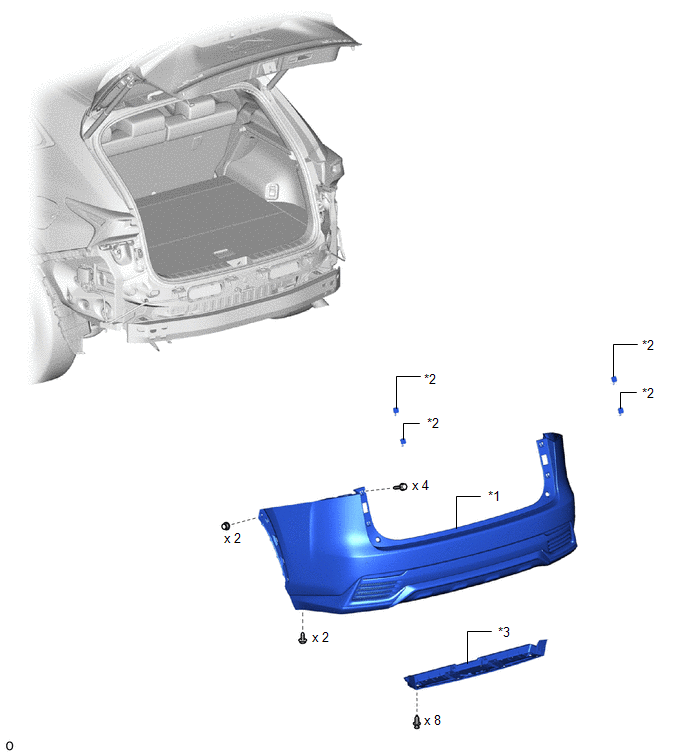
| *1 | REAR BUMPER COVER | *2 | REAR BUMPER NO. 1 PLATE |
| *3 | REAR FLOOR SIDE MEMBER COVER | - | - |
ILLUSTRATION
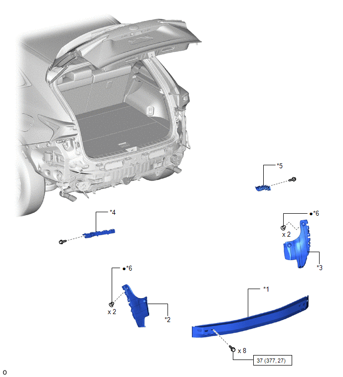
| *1 | REAR BUMPER NO. 1 REINFORCEMENT | *2 | REAR BUMPER SIDE SEAL LH |
| *3 | REAR BUMPER SIDE SEAL RH | *4 | REAR BUMPER SIDE SUPPORT LH |
| *5 | REAR BUMPER SIDE SUPPORT RH | *6 | GROMMET |
.png) | N*m (kgf*cm, ft.*lbf): Specified torque | ● | Non-reusable part |
ILLUSTRATION
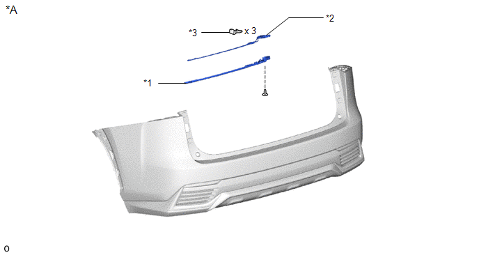
| *A | w/ Hands Free Power Back Door | - | - |
| *1 | KICK DOOR CONTROL BRACKET | *2 | KICK DOOR CONTROL SENSOR |
| *3 | OOTSIDE MOULDING RETAINER | - | - |
ILLUSTRATION
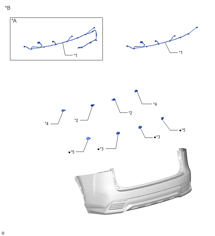
| *A | w/ Hands Free Power Back Door | *B | w/ Intuitive Parking Assist System |
| *1 | NO. 2 LUGGAGE ROOM WIRE | *2 | REAR CENTER ULTRASONIC SENSOR |
| *3 | REAR CENTER ULTRASONIC SENSOR RETAINER | *4 | REAR CORNER ULTRASONIC SENSOR |
| *5 | REAR CORNER ULTRASONIC SENSOR RETAINER | - | - |
| ● | Non-reusable part | - | - |
ILLUSTRATION
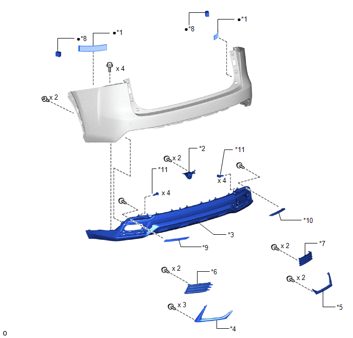
| *1 | NO. 1 MOULDING TAPE | *2 | REAR BUMPER CORNER EXTENSION RH |
| *3 | REAR BUMPER LOWER COVER | *4 | REAR BUMPER LOWER RETAINER LH |
| *5 | REAR BUMPER LOWER RETAINER RH | *6 | REAR BUMPER LOWER SIDE RETAINER LH |
| *7 | REAR BUMPER LOWER SIDE RETAINER RH | *8 | REAR BUMPER PAD |
| *9 | REFLEX REFLECTOR ASSEMBLY LH | *10 | REFLEX REFLECTOR ASSEMBLY RH |
| *11 | OUT SIDE MOULDING RETAINER | - | - |
| ● | Non-reusable part | - | - |
READ NEXT:
 Removal
REMOVAL CAUTION / NOTICE / HINT w/ Blind Spot Monitor System: HINT: If the bumper is damaged, there is a possibility that the installation area of the blind spot monitor sensor may be deformed and the
Disassembly
DISASSEMBLY PROCEDURE 1. REMOVE KICK DOOR CONTROL BRACKET (w/ Hands Free Power Back Door) Click here 2. REMOVE KICK DOOR CONTROL SENSOR (w/ Hands Free Power Back Door) Click here 3. REMOVE NO. 2 L
Reassembly
REASSEMBLY PROCEDURE 1. INSTALL REAR BUMPER PAD HINT:
When installing the rear bumper pad, heat the rear bumper cover and rear bumper pad using a heat light.
Use the same procedure described for
SEE MORE:
Smart access system with push-button
start
The following operations can be
performed simply by carrying the
electronic key (including the card
key) on your person, for example in
your pocket. The driver should
always carry the electronic key.
Locks and unlocks the doors
Locks and unlocks the back door
Starts and stops the hybrid
Removal
REMOVAL PROCEDURE 1. REMOVE CONSOLE ARMREST ASSEMBLY Click here 2. REMOVE UPPER NO. 2 CONSOLE PANEL GARNISH Click here 3. REMOVE INSTRUMENT SIDE PANEL LH Click here 4. REMOVE NO. 1 INSTRUMENT PANEL SAFETY PAD SUB-ASSEMBLY Click here 5. REMOVE NO. 1 INSTRUMENT PANEL UNDER COVER SUB-AS
