Lexus NX: Removal
REMOVAL
CAUTION / NOTICE / HINT
w/ Blind Spot Monitor System:
HINT:
If the bumper is damaged, there is a possibility that the installation area of the blind spot monitor sensor may be deformed and the blind spot monitor system may not be operating correctly, so visually inspect the blind spot monitor sensor installation area (frame, stud bolt) to make sure it is not dented or bent.
Click here .gif)
If the visual inspection finds a problem, check the installation condition of the blind spot monitor sensor, and adjust the installation position of the blind spot monitor sensor as necessary.
PROCEDURE
1. REMOVE QUARTER OUTSIDE MOULDING SUB-ASSEMBLY LH
Click here
2. REMOVE QUARTER OUTSIDE MOULDING SUB-ASSEMBLY RH
HINT:
Use the same procedure described for the LH side.
3. REMOVE NO. 5 MOULDING TAPE
Click here
4. REMOVE REAR LOWER QUARTER MOULDING PROTECTOR LH
Click here
5. REMOVE REAR LOWER QUARTER MOULDING PROTECTOR RH
HINT:
Use the same procedure described for the LH side.
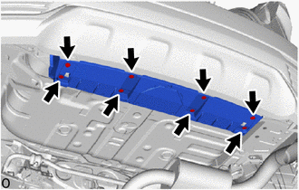
6. REMOVE REAR FLOOR SIDE MEMBER COVER
| (a) Remove the 8 clips and rear floor side member cover. |
|
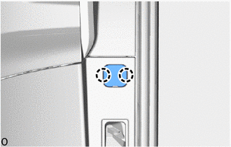
7. REMOVE REAR BUMPER NO. 1 PLATE
| (a) Detach the 2 claws and remove the rear bumper No. 1 plate. HINT: Use the same procedure for all rear bumper No. 1 plates. |
|
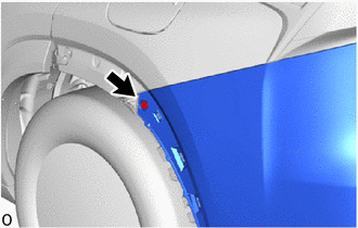
8. REMOVE REAR BUMPER COVER
| (a) Remove the clip. HINT: Use the same procedure to remove the clip on the other side. |
|
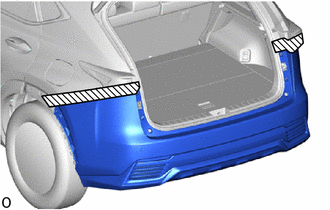
.png) | Protective Tape |
(b) Put protective tape around the rear bumper cover.
(c) Remove the 4 screws labeled A.
(d) Remove the 2 screws labeled B.
(e) w/ Intuitive Parking Assist System, Hands Free Power Back Door:
(1) Disconnect the connector.
(f) Detach the 16 claws and remove the rear bumper cover.
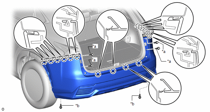
| *a | Screw A | *b | Screw B |
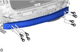
9. REMOVE REAR BUMPER NO. 1 REINFORCEMENT
| (a) Remove the 8 bolts and rear bumper No. 1 reinforcement. |
|
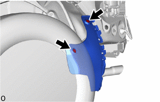
10. REMOVE REAR BUMPER SIDE SEAL LH
| (a) Remove the 2 grommets and rear bumper side seal LH. |
|
11. REMOVE REAR BUMPER SIDE SEAL RH
HINT:
Use the same procedure described for the LH side.
12. REMOVE REAR BUMPER SIDE SUPPORT LH
| (a) Remove the screw. |
|
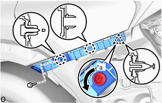
(b) Using a screwdriver, turn the clip 90° and detach the clip.
(c) Detach the 2 claws and remove the rear bumper side support LH.
13. REMOVE REAR BUMPER SIDE SUPPORT RH
HINT:
Use the same procedure described for the LH side.
READ NEXT:
 Disassembly
DISASSEMBLY PROCEDURE 1. REMOVE KICK DOOR CONTROL BRACKET (w/ Hands Free Power Back Door) Click here 2. REMOVE KICK DOOR CONTROL SENSOR (w/ Hands Free Power Back Door) Click here 3. REMOVE NO. 2 L
Reassembly
REASSEMBLY PROCEDURE 1. INSTALL REAR BUMPER PAD HINT:
When installing the rear bumper pad, heat the rear bumper cover and rear bumper pad using a heat light.
Use the same procedure described for
Installation
INSTALLATION PROCEDURE 1. INSTALL REAR BUMPER SIDE SUPPORT LH (a) Attach the 2 claws to install the rear bumper side support LH. (b) Attach the clip. (c) Install the screw. 2. INSTALL R
SEE MORE:
Certification ECU Vehicle Information Reading/Writing Process Malfunction (B15F7)
DESCRIPTION This DTC is stored when items controlled by the certification ECU cannot be customized via the audio and visual system vehicle customization screen. HINT: The certification ECU controls the smart access system with push-button start (for Entry Function) related items that are customizabl
VSC OFF Switch Circuit
DESCRIPTION The skid control ECU assembly is connected to the combination meter assembly via CAN communication. Pressing the VSC OFF switch turns off TRAC operation, and pressing and holding this switch turns off TRAC and VSC operation. If TRAC and VSC operations are turned off, the TRAC OFF message
