Lexus NX: Components
COMPONENTS
ILLUSTRATION
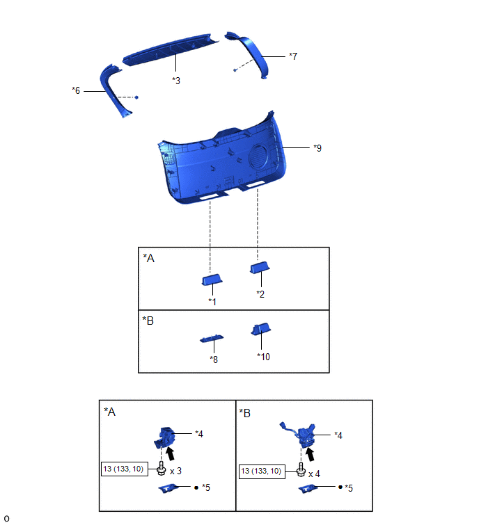
| *A | w/o Power Back Door | *B | w/ Power Back Door |
| *1 | BACK DOOR FINISH COVER LH | *2 | BACK DOOR FINISH COVER RH |
| *3 | BACK DOOR CENTER GARNISH | *4 | BACK DOOR LOCK ASSEMBLY |
| *5 | BACK DOOR LOCK COVER | *6 | BACK DOOR SIDE GARNISH LH |
| *7 | BACK DOOR SIDE GARNISH RH | *8 | BACK DOOR TRIM BASE |
| *9 | BACK DOOR TRIM BOARD ASSEMBLY | *10 | PULL HANDLE |
 | N*m (kgf*cm, ft.*lbf): Specified torque | ● | Non-reusable part |
 | MP grease | - | - |
READ NEXT:
 Removal
REMOVAL PROCEDURE 1. REMOVE BACK DOOR CENTER GARNISH Click here 2. REMOVE BACK DOOR SIDE GARNISH LH Click here 3. REMOVE BACK DOOR SIDE GARNISH RH HINT: Use the same procedure described for the LH
Inspection
INSPECTION PROCEDURE 1. INSPECT BACK DOOR LOCK ASSEMBLY (w/o Power Back Door) (a) Check the operation of the door lock motor. (1) Move the back door lock assembly to the lock position. (2) Apply au
Installation
INSTALLATION PROCEDURE 1. INSTALL BACK DOOR LOCK ASSEMBLY (w/ Power Back Door) NOTICE:
When installing a new back door lock assembly, if there is any tape stuck to it, remove the tape.
When insta
SEE MORE:
Inspection
INSPECTION PROCEDURE 1. INSPECT FRONT SEAT INNER BELT ASSEMBLY LH (a) Measure the resistance according to the value(s) in the table below. *1 Connector A *2 Connector B *3 Connector C - - *a Component without harness connected (Front Seat Inner Belt Assembly LH) - -
Removal
REMOVAL CAUTION / NOTICE / HINT HINT:
Use the same procedure for the RH and LH sides.
The following procedure is for the LH side.
NOTICE:
When the brake pedal is first depressed after replacing the brake pads or pushing back the disc brake piston, DTC C1214 may be output. As there is no m
© 2016-2026 Copyright www.lexunx.com
