Lexus NX: Disassembly
DISASSEMBLY
PROCEDURE
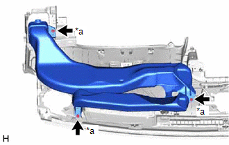
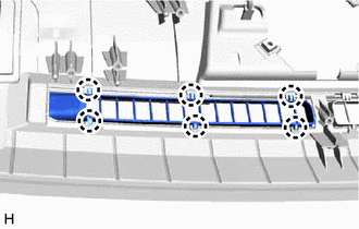
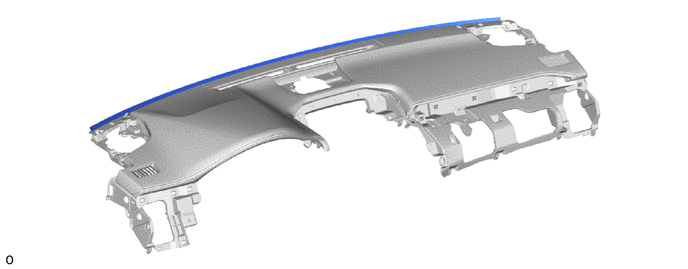
1. REMOVE NO. 1 HEATER TO REGISTER DUCT SUB-ASSEMBLY
| (a) Remove the 3 screws <A> or <B> and No. 1 heater to register duct sub-assembly. |
|
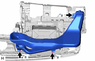
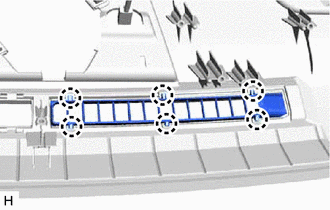
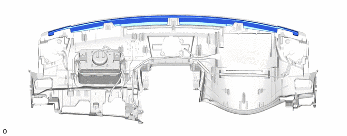
2. REMOVE NO. 2 HEATER TO REGISTER DUCT SUB-ASSEMBLY
| (a) Remove the 3 screws <A> or <B> and No. 2 heater to register duct sub-assembly. |
|
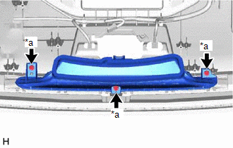
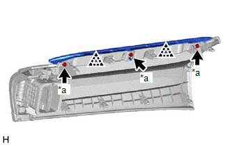
3. REMOVE DEFROSTER NOZZLE ASSEMBLY
| (a) Remove the 3 screws <A> or <B> and defroster nozzle assembly. |
|
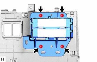
4. REMOVE METER HOOD SET BRACKET
| (a) Detach the clamp. |
|
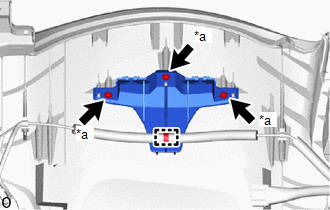
(b) Remove the 3 screws <A> or <B> and meter hood set bracket.
5. REMOVE NO. 2 DEFROSTER NOZZLE GARNISH
| (a) Detach the 6 claws and remove the No. 2 defroster nozzle garnish. |
|
6. REMOVE NO. 1 DEFROSTER NOZZLE GARNISH
| (a) Detach the 6 claws and remove the No. 1 defroster nozzle garnish. |
|
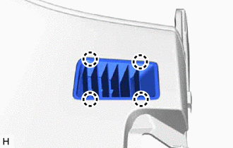
7. REMOVE SIDE DEFROSTER NOZZLE LH
| (a) Detach the 4 claws and remove the side defroster nozzle LH. |
|
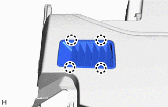
8. REMOVE SIDE DEFROSTER NOZZLE RH
| (a) Detach the 4 claws and remove the side defroster nozzle RH. |
|
9. REMOVE NO. 1 INSTRUMENT PANEL CUSHION
(a) Remove the No. 1 instrument panel cushion.
10. REMOVE NO. 2 INSTRUMENT PANEL CUSHION
(a) Remove the No. 2 instrument panel cushion.
11. REMOVE NO. 2 INSTRUMENT PANEL WIRE
Click here .gif)
12. REMOVE INSTRUMENT PANEL PASSENGER WITHOUT DOOR AIRBAG ASSEMBLY
Click here
13. REMOVE NAVIGATION ANTENNA ASSEMBLY WITH BRACKET
Click here
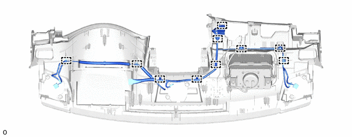
14. REMOVE INSTRUMENT PANEL WIRE
(a) Detach the clamps and remove the instrument panel wire.
15. REMOVE METER MIRROR SUB-ASSEMBLY (HEADUP DISPLAY) (w/ Headup Display)
Click here
16. REMOVE INSTRUMENT CLUSTER FINISH PANEL ASSEMBLY (w/ Headup Display)
| (a) Detach the 2 claws and 3 clips. |
|
(b) Detach the 3 guides and remove the instrument cluster finish panel assembly.
17. REMOVE NO. 2 INSTRUMENT CLUSTER FINISH PANEL GARNISH
| (a) Remove the 3 screws <A> or <B>. |
|
(b) Detach the 2 clips and remove the No. 2 instrument cluster finish panel garnish.
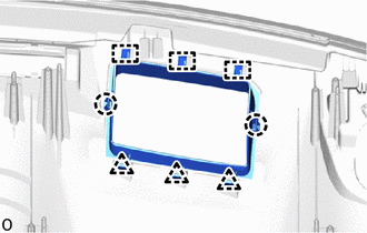
18. REMOVE LOWER NO. 2 INSTRUMENT PANEL FINISH PANEL
| (a) Remove the 4 screws and lower No. 2 instrument panel finish panel. |
|
READ NEXT:
 Reassembly
REASSEMBLY PROCEDURE 1. INSTALL LOWER NO. 2 INSTRUMENT PANEL FINISH PANEL (a) Install the lower No. 2 instrument panel finish panel with the 4 screws. 2. INSTALL NO. 2 INSTRUMENT CLUSTE
Installation
INSTALLATION CAUTION / NOTICE / HINT HINT: A bolt without a torque specification is shown in the standard bolt chart. Click here PROCEDURE 1. INSTALL UPPER INSTRUMENT PANEL SUB-ASSEMBLY (a) Attach t
SEE MORE:
Removal
REMOVAL PROCEDURE 1. REMOVE NO. 1 ENGINE UNDER COVER ASSEMBLY Click here 2. REMOVE INVERTER WITH CONVERTER ASSEMBLY Click here 3. REMOVE INVERTER WATER PUMP WITH MOTOR ASSEMBLY Click here 4. REMOVE INVERTER BRACKET ASSEMBLY Click here 5. DISCONNECT WIRE HARNESS (a) Disconnect the 4
Before driving
Observe the following before starting
off in the vehicle to ensure
safety of driving.
Installing floor mats
Use only floor mats designed specifically
for vehicles of the same model
and model year as your vehicle. Fix
them securely in place onto the carpet.
1. Insert the retaining hooks (clip
