Lexus NX: Components
Lexus NX Service Manual / Audio & Visual & Telematics / Audio / Video / Radio Antenna Cord / Components
COMPONENTS
ILLUSTRATION
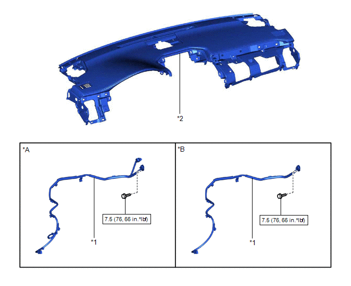
| *A | for Type A | *B | for Type B |
| *1 | NO. 1 ANTENNA CORD SUB-ASSEMBLY | *2 | UPPER INSTRUMENT PANEL SUB-ASSEMBLY |
.png) | N*m (kgf*cm, ft.*lbf): Specified torque | - | - |
ILLUSTRATION
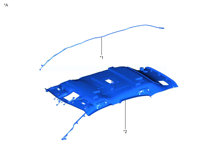
| *A | for Normal Roof | - | - |
| *1 | NO. 2 ANTENNA CORD SUB-ASSEMBLY | *2 | ROOF HEADLINING ASSEMBLY |
ILLUSTRATION
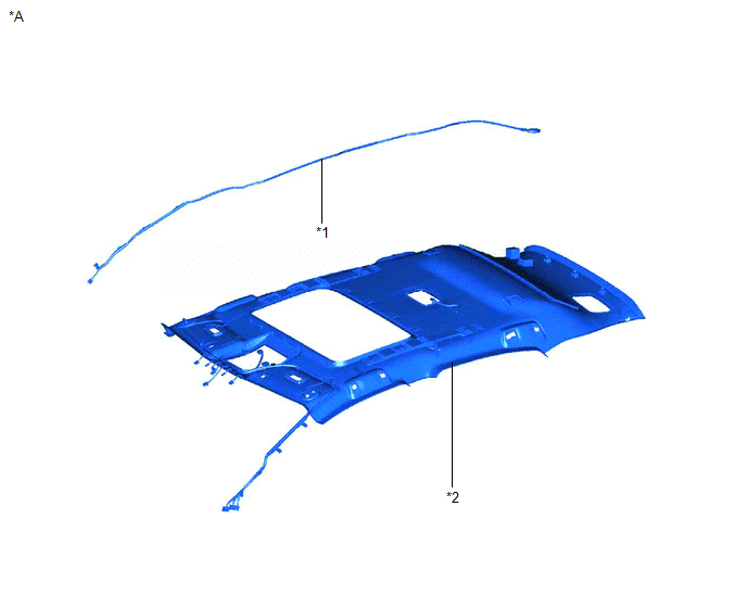
| *A | for Sliding Roof | - | - |
| *1 | NO. 2 ANTENNA CORD SUB-ASSEMBLY | *2 | ROOF HEADLINING ASSEMBLY |
ILLUSTRATION
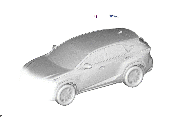
| *1 | NO. 4 ANTENNA CORD SUB-ASSEMBLY | - | - |
READ NEXT:
 Removal
REMOVAL PROCEDURE 1. PRECAUTION CAUTION: Be sure to read Precaution thoroughly before serving. Click here NOTICE: After turning the power switch off, there may be a waiting time before disconnecting
Installation
INSTALLATION PROCEDURE 1. INSTALL NO. 4 ANTENNA CORD SUB-ASSEMBLY (a) Attach the 2 clamps and guide to install the No. 4 antenna cord sub-assembly. (b) Install the bolt and attach the 2 clamps to inst
SEE MORE:
Operation Check
OPERATION CHECK ICS OFF INDICATOR LIGHT OPERATION CHECK (a) Turn the power switch on (IG). (b) Turn the intelligent clearance sonar system off and confirm that the ICS OFF indicator in the combination meter illuminates. HINT: If the intelligent clearance sonar system is not set to off in the custom
System Diagram
SYSTEM DIAGRAM Communication Table Transmitting ECU Receiver ECU Signal Communication Method Certification ECU (Smart Key ECU Assembly) Main Body ECU (Multiplex Network Body ECU) Back door opener switch assembly signal CAN Main Body ECU (Multiplex Network Body ECU) Multiple
© 2016-2026 Copyright www.lexunx.com
