Lexus NX: Components
COMPONENTS
ILLUSTRATION
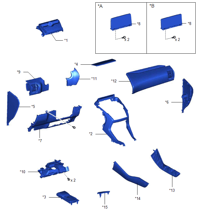
| *A | for 8 Inch Display | *B | for 10.3 Inch Display |
| *1 | AIR CONDITIONING CONTROL ASSEMBLY | *2 | CENTER INSTRUMENT CLUSTER FINISH PANEL ASSEMBLY |
| *3 | CONSOLE ARMREST ASSEMBLY | *4 | INSTRUMENT PANEL FINISH PLATE |
| *5 | INSTRUMENT SIDE PANEL LH | *6 | INSTRUMENT SIDE PANEL RH |
| *7 | LOWER NO. 1 INSTRUMENT PANEL FINISH PANEL | *8 | MULTI-DISPLAY ASSEMBLY WITH BRACKET |
| *9 | NO. 1 INSTRUMENT PANEL SAFETY PAD SUB-ASSEMBLY | *10 | NO. 1 INSTRUMENT PANEL UNDER COVER SUB-ASSEMBLY |
| *11 | NO. 1 SWITCH HOLE BASE | *12 | NO. 2 INSTRUMENT PANEL SAFETY PAD SUB-ASSEMBLY |
| *13 | UPPER NO. 1 CONSOLE PANEL GARNISH | *14 | UPPER NO. 2 CONSOLE PANEL GARNISH |
| *15 | UPPER REAR CONSOLE PANEL | - | - |
ILLUSTRATION
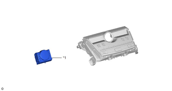
| *1 | CLOCK ASSEMBLY | - | - |
READ NEXT:
 Removal
REMOVAL PROCEDURE 1. REMOVE CONSOLE ARMREST ASSEMBLY Click here 2. REMOVE UPPER REAR CONSOLE PANEL Click here 3. REMOVE UPPER NO. 2 CONSOLE PANEL GARNISH Click here 4. REMOVE UPPER NO. 1 CONS
Inspection
INSPECTION PROCEDURE 1. INSPECT CLOCK ASSEMBLY (a) Check the illumination. Apply auxiliary battery voltage to the connector and check the illumination condition. OK: Measurement Condition Spe
Installation
INSTALLATION PROCEDURE 1. INSTALL CLOCK ASSEMBLY (a) Attach the 2 claws to install the clock assembly. 2. INSTALL AIR CONDITIONING CONTROL ASSEMBLY (a) Connect the connectors.
SEE MORE:
Components
COMPONENTS ILLUSTRATION *1 DECK FLOOR BOX LH *2 NO. 3 DECK BOARD SUB-ASSEMBLY *3 REAR DECK FLOOR BOX *4 NEGATIVE AUXILIARY BATTERY TERMINAL N*m (kgf*cm, ft.*lbf): Specified torque - - ILLUSTRATION *1 REAR DOOR INNER GLASS WEATHERSTRIP LH *2 REAR DOOR INSID
Customize Parameters
CUSTOMIZE PARAMETERS CUSTOMIZE ROAD SIGN ASSIST SYSTEM NOTICE: Be sure to make a note of the current settings before customizing. (a) Customizing with the multi-information display (1) Turn the power switch on (IG). (2) Using the steering pad switches, change the customize settings. HINT: Each item
© 2016-2026 Copyright www.lexunx.com
