Lexus NX: Removal
REMOVAL
PROCEDURE
1. REMOVE CONSOLE ARMREST ASSEMBLY
Click here .gif)
2. REMOVE UPPER REAR CONSOLE PANEL
Click here
3. REMOVE UPPER NO. 2 CONSOLE PANEL GARNISH
Click here
4. REMOVE UPPER NO. 1 CONSOLE PANEL GARNISH
Click here
5. REMOVE INSTRUMENT SIDE PANEL LH
Click here
6. REMOVE NO. 1 INSTRUMENT PANEL SAFETY PAD SUB-ASSEMBLY
Click here
7. REMOVE NO. 1 INSTRUMENT PANEL UNDER COVER SUB-ASSEMBLY
Click here
8. REMOVE LOWER NO. 1 INSTRUMENT PANEL FINISH PANEL
Click here
9. REMOVE NO. 1 SWITCH HOLE BASE
Click here
10. REMOVE INSTRUMENT SIDE PANEL RH
Click here
11. REMOVE NO. 2 INSTRUMENT PANEL SAFETY PAD SUB-ASSEMBLY
Click here
12. REMOVE INSTRUMENT PANEL FINISH PLATE
Click here
13. REMOVE MULTI-DISPLAY ASSEMBLY WITH BRACKET
Click here
14. REMOVE CENTER INSTRUMENT CLUSTER FINISH PANEL ASSEMBLY
Click here
15. REMOVE AIR CONDITIONING CONTROL ASSEMBLY
| (a) Pull the air conditioning control assembly in the direction indicated by the arrows shown in the illustration to detach the 6 clips. |
|
.png)
(b) Disconnect the connectors and remove the air conditioning control assembly.
16. REMOVE CLOCK ASSEMBLY
(a) Insert a thin-bladed screwdriver with its tip wrapped with protective tape at the position shown in the illustration, detach the 2 claws and remove the clock assembly.
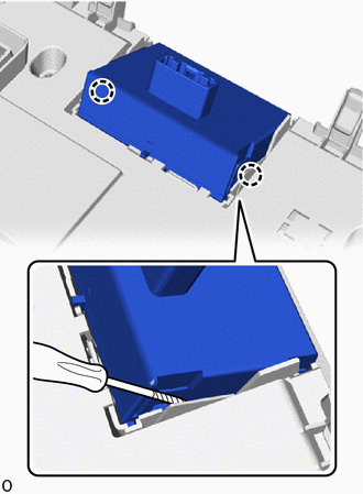
.png) | Protective Tape |
READ NEXT:
 Inspection
INSPECTION PROCEDURE 1. INSPECT CLOCK ASSEMBLY (a) Check the illumination. Apply auxiliary battery voltage to the connector and check the illumination condition. OK: Measurement Condition Spe
Installation
INSTALLATION PROCEDURE 1. INSTALL CLOCK ASSEMBLY (a) Attach the 2 claws to install the clock assembly. 2. INSTALL AIR CONDITIONING CONTROL ASSEMBLY (a) Connect the connectors.
SEE MORE:
Removal
REMOVAL PROCEDURE 1. REMOVE LOWER INSTRUMENT PANEL Click here 2. REMOVE NO. 1 AIR DUCT Click here 3. REMOVE QUICK HEATER ASSEMBLY (a) Detach the clamp and disconnect the 2 connectors. (b) Remove the screw and quick heater assembly.
Inspection
INSPECTION CAUTION / NOTICE / HINT HINT:
Use the same procedure for the RH and LH sides.
The procedure listed below is for the LH side.
PROCEDURE 1. INSPECT REAR NO. 1 SUSPENSION ARM ASSEMBLY LH (a) Inspect the turning torque of the ball joint. (1) Install the installation nut to the ball j
