Lexus NX: Components
Lexus NX Service Manual / Vehicle Interior / Meter / Gauge / Display / Headup Display Switch / Components
COMPONENTS
ILLUSTRATION
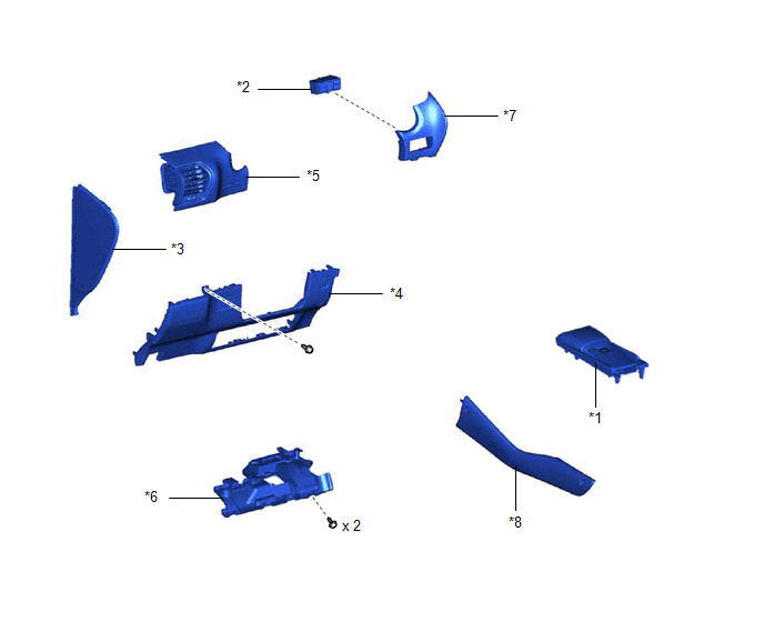
| *1 | CONSOLE ARMREST ASSEMBLY | *2 | HEADUP DISPLAY SWITCH ASSEMBLY |
| *3 | INSTRUMENT SIDE PANEL LH | *4 | LOWER NO. 1 INSTRUMENT PANEL FINISH PANEL |
| *5 | NO. 1 INSTRUMENT PANEL SAFETY PAD SUB-ASSEMBLY | *6 | NO. 1 INSTRUMENT PANEL UNDER COVER SUB-ASSEMBLY |
| *7 | NO. 1 SWITCH HOLE BASE | *8 | UPPER NO. 2 CONSOLE PANEL GARNISH |
READ NEXT:
 Removal
REMOVAL PROCEDURE 1. REMOVE CONSOLE ARMREST ASSEMBLY Click here 2. REMOVE UPPER NO. 2 CONSOLE PANEL GARNISH Click here 3. REMOVE INSTRUMENT SIDE PANEL LH Click here 4. REMOVE NO. 1 INSTRUM
Inspection
INSPECTION PROCEDURE 1. INSPECT HEADUP DISPLAY SWITCH ASSEMBLY *1 HUD Switch *2 TILT Switch *3 RHEOSTAT Switch *4 DISP Switch *a Component without harness connected (Head
Installation
INSTALLATION PROCEDURE 1. INSTALL HEADUP DISPLAY SWITCH ASSEMBLY (a) Attach the 4 claws to install the headup display switch assembly. 2. INSTALL NO. 1 SWITCH HOLE BASE Click here 3
SEE MORE:
Steering Angle Sensor Circuit (C1231)
DESCRIPTION The skid control ECU (brake booster with master cylinder assembly) receives steering sensor signals via CAN communication. When a malfunction occurs in the communication line with the steering sensor, DTC U0126 (Lost Communication with Steering Angle Sensor Module) is stored. DTC No.
Installation
INSTALLATION CAUTION / NOTICE / HINT HINT:
Use the same procedure for the RH and LH sides.
The procedure listed below is for the LH side.
PROCEDURE 1. INSTALL REAR DRIVE SHAFT ASSEMBLY LH (a) Align the matchmarks on the rear drive shaft assembly LH and rear axle hub and bearing assembly,
© 2016-2026 Copyright www.lexunx.com
