Lexus NX: Inspection
INSPECTION
PROCEDURE
1. INSPECT HEADUP DISPLAY SWITCH ASSEMBLY
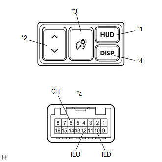
| *1 | HUD Switch |
| *2 | TILT Switch |
| *3 | RHEOSTAT Switch |
| *4 | DISP Switch |
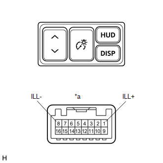
| *a | Component without harness connected (Headup Display Switch Assembly) |
(a) Check the resistance.
Measure the resistance according to the value(s) in the table below.
Standard Resistance:
| Tester Connection | Switch Condition | Specified Condition |
|---|---|---|
| 12 (ILU) - 6 (CH) | HUD switch off (Not pushed) | 100 kΩ |
| 10 (ILD) - 6 (CH) | 100 kΩ | |
| 12 (ILU) - 6 (CH) | HUD switch on (Pushed) | Below 1 Ω |
| 10 (ILD) - 6 (CH) | 100 kΩ | |
| 12 (ILU) - 6 (CH) | TILT switch (UP) on (Pushed) | 100 kΩ |
| 10 (ILD) - 6 (CH) | 3210 Ω | |
| 12 (ILU) - 6 (CH) | TILT switch off (Not pushed) | 100 kΩ |
| 10 (ILD) - 6 (CH) | 100 kΩ | |
| 12 (ILU) - 6 (CH) | TILT switch (DOWN) on (Pushed) | 100 kΩ |
| 10 (ILD) - 6 (CH) | 1010 Ω | |
| 12 (ILU) - 6 (CH) | RHEOSTAT switch (ILL UP) on (Pushed) | 100 kΩ |
| 10 (ILD) - 6 (CH) | 330 Ω | |
| 12 (ILU) - 6 (CH) | RHEOSTAT switch off (Not pushed) | 100 kΩ |
| 10 (ILD) - 6 (CH) | 100 kΩ | |
| 12 (ILU) - 6 (CH) | RHEOSTAT switch (ILL DOWN) on (Pushed) | 100 kΩ |
| 10 (ILD) - 6 (CH) | Below 1 Ω | |
| 12 (ILU) - 6 (CH) | DISP switch off (Not pushed) | 100 kΩ |
| 10 (ILD) - 6 (CH) | 100 kΩ | |
| 12 (ILU) - 6 (CH) | DISP switch on (Pushed) | 330 Ω |
| 10 (ILD) - 6 (CH) | 100 kΩ |
If the result is not as specified, replace the headup display switch assembly.
| (b) Check the illumination. Apply battery voltage to the connector and check the illumination condition. OK:
If the result is not as specified, replace the headup display switch assembly. |
|
READ NEXT:
 Installation
INSTALLATION PROCEDURE 1. INSTALL HEADUP DISPLAY SWITCH ASSEMBLY (a) Attach the 4 claws to install the headup display switch assembly. 2. INSTALL NO. 1 SWITCH HOLE BASE Click here 3
Parts Location
PARTS LOCATION ILLUSTRATION *1 HEADUP DISPLAY SWITCH ASSEMBLY *2 METER MIRROR SUB-ASSEMBLY *3 FORWARD RECOGNITION CAMERA *4 NO. 2 ENGINE ROOM RELAY BLOCK - ECU-B NO.1 FUSE *5
SEE MORE:
Lost Communication with "Door Control Module B" (U0200)
DESCRIPTION DTC No. Detection Item DTC Detection Condition Trouble Area DTC Output from U0200 Lost Communication with "Door Control Module B" There is no communication from the outer mirror control ECU assembly RH.
Power source circuit of outer mirror control ECU assembly RH
Components
COMPONENTS ILLUSTRATION *1 LOWER OUTER MIRROR COVER LH *2 OUTER MIRROR BEZEL LH *3 OUTER MIRROR COVER LH *4 OUTER MIRROR LH *5 SIDE TURN SIGNAL LIGHT ASSEMBLY LH - -
