Lexus NX: Installation
Lexus NX Service Manual / Vehicle Interior / Meter / Gauge / Display / Headup Display Switch / Installation
INSTALLATION
PROCEDURE
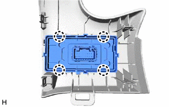
1. INSTALL HEADUP DISPLAY SWITCH ASSEMBLY
| (a) Attach the 4 claws to install the headup display switch assembly. |
|
2. INSTALL NO. 1 SWITCH HOLE BASE
Click here .gif)
3. INSTALL LOWER NO. 1 INSTRUMENT PANEL FINISH PANEL
Click here
4. INSTALL NO. 1 INSTRUMENT PANEL UNDER COVER SUB-ASSEMBLY
Click here
5. INSTALL NO. 1 INSTRUMENT PANEL SAFETY PAD SUB-ASSEMBLY
Click here
6. INSTALL INSTRUMENT SIDE PANEL LH
Click here
7. INSTALL UPPER NO. 2 CONSOLE PANEL GARNISH
Click here
8. INSTALL CONSOLE ARMREST ASSEMBLY
Click here
READ NEXT:
 Parts Location
PARTS LOCATION ILLUSTRATION *1 HEADUP DISPLAY SWITCH ASSEMBLY *2 METER MIRROR SUB-ASSEMBLY *3 FORWARD RECOGNITION CAMERA *4 NO. 2 ENGINE ROOM RELAY BLOCK - ECU-B NO.1 FUSE *5
System Diagram
SYSTEM DIAGRAM
SEE MORE:
Road Test
ROAD TEST HINT:
The dynamic radar cruise control system has 2 cruise control modes: constant speed control mode and vehicle-to-vehicle distance control mode.
Vehicle-to-vehicle distance control mode is selected by default when the dynamic radar cruise control system is turned on using the cruis
Fuel Sender Open Detected (B1500)
DESCRIPTION This DTC is stored when the combination meter detects a fuel sender gauge malfunction. DTC No. Detection Item DTC Detection Condition Trouble Area B1500 Fuel Sender Open Detected Both conditions are met:
IG voltage is 10.5 V or higher.
Average input signal of fuel s
© 2016-2026 Copyright www.lexunx.com
