Lexus NX: Components
COMPONENTS
ILLUSTRATION
.png)
| *1 | DECK FLOOR BOX LH | *2 | NO. 3 DECK BOARD SUB-ASSEMBLY |
| *3 | REAR DECK FLOOR BOX | *4 | AUXILIARY BATTERY NEGATIVE TERMINAL |
.png) | N*m (kgf*cm, ft.*lbf): Specified torque | - | - |
ILLUSTRATION
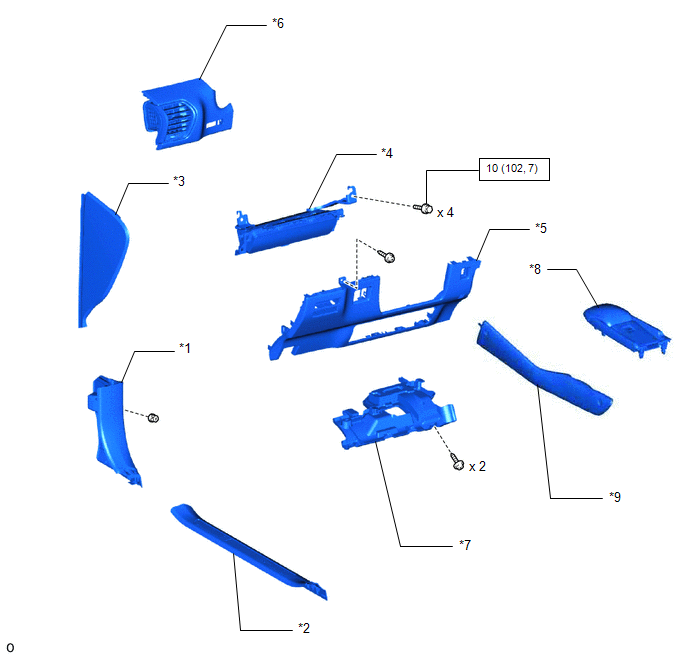
| *1 | COWL SIDE TRIM BOARD LH | *2 | DOOR SCUFF PLATE ASSEMBLY LH |
| *3 | INSTRUMENT SIDE PANEL LH | *4 | LOWER NO. 1 INSTRUMENT PANEL AIRBAG ASSEMBLY |
| *5 | LOWER NO. 1 INSTRUMENT PANEL FINISH PANEL | *6 | NO. 1 INSTRUMENT PANEL SAFETY PAD SUB-ASSEMBLY |
| *7 | NO. 1 INSTRUMENT PANEL UNDER COVER SUB-ASSEMBLY | *8 | REAR CONSOLE ARMREST ASSEMBLY |
| *9 | UPPER NO. 2 CONSOLE PANEL GARNISH | - | - |
| | N*m (kgf*cm, ft.*lbf): Specified torque | - | - |
READ NEXT:
 On-vehicle Inspection
ON-VEHICLE INSPECTION CAUTION / NOTICE / HINT CAUTION: Be sure to follow the correct removal and installation procedures of the lower No. 1 instrument panel airbag assembly. PROCEDURE 1. INSPECT LOWER
Removal
REMOVAL PROCEDURE 1. REMOVE NO. 3 DECK BOARD SUB-ASSEMBLY Click here 2. REMOVE REAR DECK FLOOR BOX Click here 3. REMOVE DECK FLOOR BOX LH Click here 4. PRECAUTION CAUTION: Be sure to read Precau
Installation
INSTALLATION CAUTION / NOTICE / HINT HINT:
Use the same procedure for RHD and LHD vehicles.
The procedures listed below are for LHD vehicles.
PROCEDURE 1. INSTALL LOWER NO. 1 INSTRUMENT PANEL
SEE MORE:
Operation Check
OPERATION CHECK AUTOMATIC LIGHT CONTROL SYSTEM OPERATION CHECK (a) Turn the power switch on (IG). (b) Turn the headlight dimmer switch to the AUTO position. (c) Cover the automatic light control sensor. (d) Check that the taillights and low beam headlights come on. (e) Uncover the automatic light co
Blind Spot Monitor Sensor
RemovalREMOVAL CAUTION / NOTICE / HINT NOTICE:
Avoid any impact to the blind spot monitor sensor.
Do not drop the blind spot monitor sensor. If it is dropped, replace it with a new one.
PROCEDURE 1. REMOVE REAR BUMPER COVER Click here 2. REMOVE BLIND SPOT MONITOR SENSOR LH (a) Remove the
© 2016-2026 Copyright www.lexunx.com
