Lexus NX: Components
COMPONENTS
ILLUSTRATION
.png)
| *1 | DECK FLOOR BOX LH | *2 | NO. 3 DECK BOARD SUB-ASSEMBLY |
| *3 | REAR DECK FLOOR BOX | *4 | NEGATIVE AUXILIARY BATTERY TERMINAL |
.png) | N*m (kgf*cm, ft.*lbf): Specified torque | - | - |
ILLUSTRATION
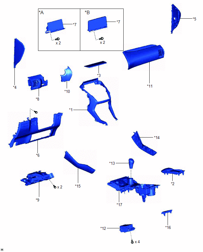
| *1 | CENTER INSTRUMENT CLUSTER FINISH PANEL ASSEMBLY | *2 | CONSOLE ARMREST ASSEMBLY |
| *3 | INSTRUMENT PANEL FINISH PLATE | *4 | INSTRUMENT SIDE PANEL LH |
| *5 | INSTRUMENT SIDE PANEL RH | *6 | LOWER NO. 1 INSTRUMENT PANEL FINISH PANEL |
| *7 | MULTI-DISPLAY ASSEMBLY WITH BRACKET | *8 | NO. 1 INSTRUMENT PANEL SAFETY PAD SUB-ASSEMBLY |
| *9 | NO. 1 INSTRUMENT PANEL UNDER COVER SUB-ASSEMBLY | *10 | NO. 1 SWITCH HOLE BASE |
| *11 | NO. 2 INSTRUMENT PANEL SAFETY PAD SUB-ASSEMBLY | *12 | REMOTE OPERATION CONTROLLER ASSEMBLY |
| *13 | SHIFT LEVER KNOB SUB-ASSEMBLY | *14 | UPPER NO. 1 CONSOLE PANEL GARNISH |
| *15 | UPPER NO. 2 CONSOLE PANEL GARNISH | *16 | UPPER REAR CONSOLE PANEL |
| *17 | UPPER REAR CONSOLE PANEL SUB-ASSEMBLY | - | - |
READ NEXT:
 Removal
REMOVAL PROCEDURE 1. REMOVE DECK BOARD ASSEMBLY Click here 2. REMOVE NO. 3 DECK BOARD SUB-ASSEMBLY Click here 3. REMOVE REAR DECK FLOOR BOX Click here 4. REMOVE DECK FLOOR BOX LH Click here 5.
Installation
INSTALLATION PROCEDURE 1. INSTALL REMOTE OPERATION CONTROLLER ASSEMBLY (a) Install the remote operation controller assembly with the 4 bolts. 2. INSTALL UPPER REAR CONSOLE PANEL SUB-ASSEMBLY Click her
Telephone Microphone Assembly
ComponentsCOMPONENTS ILLUSTRATION *1 TELEPHONE MICROPHONE ASSEMBLY - -
SEE MORE:
Components
COMPONENTS ILLUSTRATION *1 ELECTRICAL KEY ANTENNA *2 QUARTER OUTSIDE MOULDING SUB-ASSEMBLY LH *3 QUARTER OUTSIDE MOULDING SUB-ASSEMBLY RH *4 REAR BUMPER COVER *5 REAR FLOOR SIDE MEMBER COVER - - N*m (kgf*cm, ft.*lbf): Specified torque - -
Inspection
INSPECTION PROCEDURE 1. INSPECT INTEGRATION CONTROL AND PANEL ASSEMBLY (ABSORBER CONTROL SWITCH) (a) Measure the resistance according to the value(s) in the table below. Standard Resistance: Tester Connection Switch Condition Specified Condition 8 (B) - 1 (GND) Normal position ON
