Lexus NX: Removal
REMOVAL
PROCEDURE
1. REMOVE DECK BOARD ASSEMBLY
Click here .gif)
2. REMOVE NO. 3 DECK BOARD SUB-ASSEMBLY
Click here
3. REMOVE REAR DECK FLOOR BOX
Click here
4. REMOVE DECK FLOOR BOX LH
Click here
5. PRECAUTION
CAUTION:
Be sure to read Precaution thoroughly before serving.
Click here
NOTICE:
After turning the power switch off, there may be a waiting time before disconnecting the negative (-) auxiliary battery terminal.
Click here
6. DISCONNECT CABLE FROM NEGATIVE AUXILIARY BATTERY TERMINAL
CAUTION:
- Wait at least 90 seconds after disconnecting the cable from the negative (-) auxiliary battery terminal to disable the SRS system.
- If the airbag deploys for any reason. it may cause a serious accident.
7. REMOVE INSTRUMENT PANEL FINISH PLATE
Click here
8. REMOVE MULTI-DISPLAY ASSEMBLY WITH BRACKET
Click here
9. REMOVE UPPER NO. 1 CONSOLE PANEL GARNISH
Click here
10. REMOVE UPPER NO. 2 CONSOLE PANEL GARNISH
Click here
11. REMOVE INSTRUMENT SIDE PANEL RH
Click here
12. REMOVE INSTRUMENT SIDE PANEL LH
Click here
13. REMOVE NO. 1 INSTRUMENT PANEL SAFETY PAD SUB-ASSEMBLY
Click here
14. REMOVE NO. 1 SWITCH HOLE BASE
Click here
15. REMOVE NO. 1 INSTRUMENT PANEL UNDER COVER SUB-ASSEMBLY
Click here
16. REMOVE LOWER NO. 1 INSTRUMENT PANEL FINISH PANEL
Click here
17. REMOVE NO. 2 INSTRUMENT PANEL SAFETY PAD SUB-ASSEMBLY
Click here
18. REMOVE CENTER INSTRUMENT CLUSTER FINISH PANEL ASSEMBLY
Click here
19. REMOVE SHIFT LEVER KNOB SUB-ASSEMBLY
Click here
20. REMOVE CONSOLE ARMREST ASSEMBLY
Click here
21. REMOVE UPPER REAR CONSOLE PANEL
Click here
22. REMOVE UPPER REAR CONSOLE PANEL SUB-ASSEMBLY
Click here
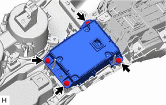
23. REMOVE REMOTE OPERATION CONTROLLER ASSEMBLY
| (a) Remove the 4 bolts and remote operation controller assembly. |
|
READ NEXT:
 Installation
INSTALLATION PROCEDURE 1. INSTALL REMOTE OPERATION CONTROLLER ASSEMBLY (a) Install the remote operation controller assembly with the 4 bolts. 2. INSTALL UPPER REAR CONSOLE PANEL SUB-ASSEMBLY Click her
Telephone Microphone Assembly
ComponentsCOMPONENTS ILLUSTRATION *1 TELEPHONE MICROPHONE ASSEMBLY - -
SEE MORE:
On-vehicle Inspection
ON-VEHICLE INSPECTION PROCEDURE 1. CHECK STEERING EFFORT (TORQUE) CAUTION: These service operations may affect the SRS airbags. Be sure to read the precautionary notices concerning the SRS airbag system before servicing. Click here (a) Stop the vehicle on a level, paved surface and align the whee
Test Mode Procedure
TEST MODE PROCEDURE TEST MODE PROCEDURE NOTICE:
After replacing the absorber control ECU, it is necessary to perform registration of vehicle identification information. Vehicle identification information is automatically acquired when the system enters test mode.
When vehicle identification inf
