Lexus NX: Cooler Expansion Valve
Components
COMPONENTS
ILLUSTRATION
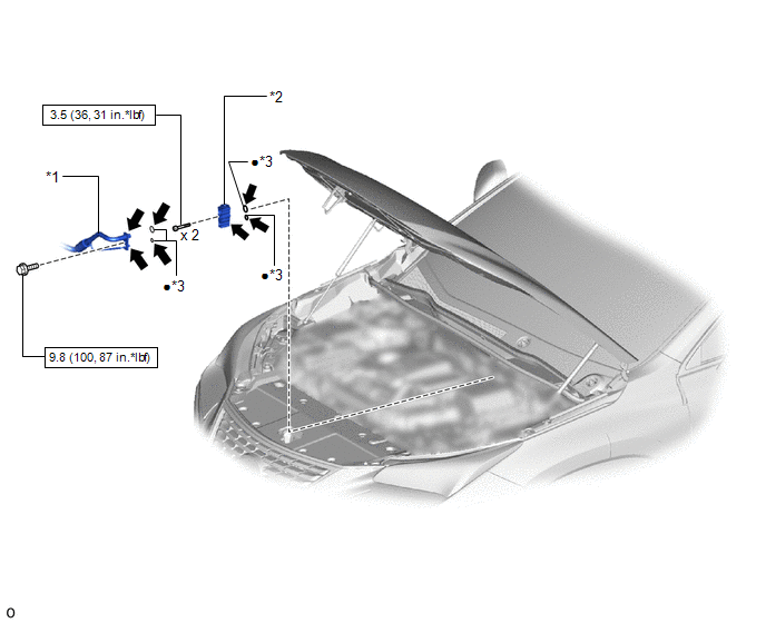
| *1 | AIR CONDITIONER TUBE AND ACCESSORY ASSEMBLY | *2 | COOLER EXPANSION VALVE |
| *3 | O-RING | - | - |
.png) | N*m (kgf*cm, ft.*lbf): Specified torque | ● | Non-reusable part |
.png) | Compressor oil ND-OIL 11 or equivalent | - | - |
Removal
REMOVAL
PROCEDURE
1. RECOVER REFRIGERANT FROM REFRIGERATION SYSTEM
Click here .gif)
2. DISCONNECT AIR CONDITIONER TUBE AND ACCESSORY ASSEMBLY
Click here
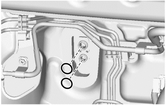
3. REMOVE COOLER EXPANSION VALVE
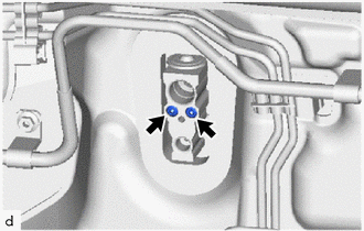
| (a) Using a 4 mm hexagon wrench, remove the 2 hexagon bolts. |
|
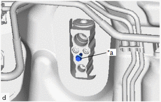
| (b) Temporarily install the 6 mm bolt halfway to the cooler expansion valve. |
|
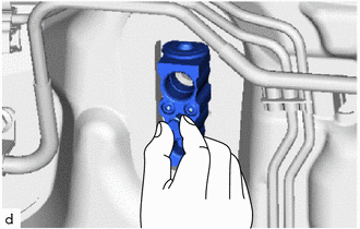
| (c) Hold the bolt and pull it to remove the cooler expansion valve as shown in the illustration. |
|
| (d) Remove the 2 O-rings. |
|
Installation
INSTALLATION
PROCEDURE
1. INSTALL COOLER EXPANSION VALVE
(a) Apply sufficient compressor oil to 2 new O-rings and the fitting surfaces of the cooler expansion valve.
Compressor Oil:
ND-OIL 11 or equivalent
(b) Install 2 new O-rings.
NOTICE:
Keep the O-rings and O-ring fitting surfaces free of foreign matter.
(c) Temporarily install the cooler expansion valve.
(d) Using a 4 mm hexagon wrench, install the cooler expansion valve with the 2 hexagon bolts.
Torque:
3.5 N·m {36 kgf·cm, 31 in·lbf}
2. CONNECT AIR CONDITIONER TUBE AND ACCESSORY ASSEMBLY
Click here .gif)
3. CHARGE AIR CONDITIONING SYSTEM WITH REFRIGERANT
Click here
4. WARM UP COMPRESSOR
Click here
5. INSPECT FOR REFRIGERANT LEAK
Click here
READ NEXT:
 Front Blower Motor
ComponentsCOMPONENTS ILLUSTRATION *1 BLOWER WITH FAN MOTOR SUB-ASSEMBLY *2 NO. 2 INSTRUMENT PANEL UNDER COVER SUB-ASSEMBLY RemovalREMOVAL PROCEDURE 1. REMOVE NO. 2 INSTRUMENT PANEL UNDE
Components
COMPONENTS ILLUSTRATION *1 COOLER EXPANSION VALVE *2 NO. 1 COOLER EVAPORATOR SUB-ASSEMBLY *3 NO. 1 COOLER THERMISTOR *4 UPPER HEATER CASE *5 LOWER HEATER CASE *6 O-RING
SEE MORE:
Components
COMPONENTS ILLUSTRATION *1 NO. 1 ENGINE UNDER COVER ASSEMBLY - - ILLUSTRATION *1 SHIFT LEVER POSITION SENSOR *2 TRANSMISSION CONTROL CABLE ASSEMBLY *3 CONTROL SHAFT LEVER *4 LOCK PLATE *5 WASHER *6 CLIP N*m (kgf*cm, ft.*lbf): Specified torque ●
Rear Door RH ECU Communication Stop (B2323)
DESCRIPTION This DTC is output when LIN communication between the rear power window regulator motor assembly RH and main body ECU (multiplex network body ECU) stops for 10 seconds or more. DTC No. Detection Item DTC Detection Condition Trouble Area B2323 Rear Door RH ECU Communication
