Lexus NX: Removal
REMOVAL
PROCEDURE
1. PRECAUTION
NOTICE:
After turning the power switch off, waiting time may be required before disconnecting the cable from the negative (-) auxiliary battery terminal. Therefore, make sure to read the disconnecting the cable from the negative (-) auxiliary battery terminal notices before proceeding with work.
Click here .gif)
2. REMOVE NO. 3 DECK BOARD SUB-ASSEMBLY
Click here
3. REMOVE REAR DECK FLOOR BOX
Click here
4. REMOVE DECK FLOOR BOX LH
Click here
5. DISCONNECT CABLE FROM NEGATIVE AUXILIARY BATTERY TERMINAL
NOTICE:
When disconnecting the cable, some systems need to be initialized after the cable is reconnected.
Click here
6. REMOVE AIR CLEANER CAP AND HOSE
Click here
7. REMOVE AIR CLEANER FILTER ELEMENT SUB-ASSEMBLY
(a) Remove the air cleaner filter element sub-assembly from the air cleaner case sub-assembly.
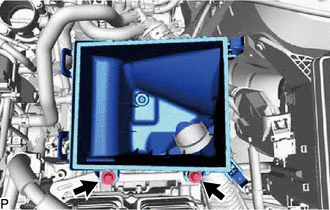
8. REMOVE AIR CLEANER CASE SUB-ASSEMBLY
| (a) Remove the 2 bolts and the air cleaner case sub-assembly. |
|
9. REMOVE ECM
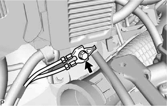
| (a) Remove the bolt and disconnect the wire harness from the No. 2 ECM bracket. |
|
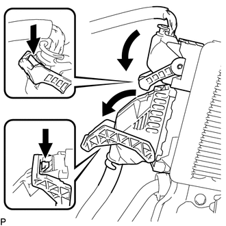
| (b) Disengage the lock, pull down the lever and disconnect the 2 connectors from the ECM. NOTICE: After disconnecting the connectors, make sure that dirt, water or other foreign matter does not contact the connecting parts of the connectors. |
|
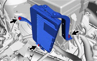
| (c) Remove the 3 bolts and ECM. |
|
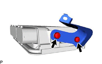
10. REMOVE NO. 1 ECM BRACKET
| (a) Remove the 2 screws and the No. 1 ECM bracket from the ECM. |
|
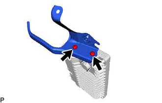
11. REMOVE NO. 2 ECM BRACKET
| (a) Remove the 2 screws and the No. 2 ECM bracket from the ECM. |
|
READ NEXT:
 Installation
INSTALLATION PROCEDURE 1. INSTALL NO. 2 ECM BRACKET (a) Install the No. 2 ECM bracket to the ECM with the 2 screws. Torque: 3.0 N·m {31 kgf·cm, 27 in·lbf} 2. INSTALL NO. 1 ECM BRACKET (a) Install
Components
COMPONENTS ILLUSTRATION *1 ENGINE COOLANT TEMPERATURE SENSOR *2 NO. 1 ENGINE COVER SUB-ASSEMBLY *3 GROUND WIRE *4 GASKET N*m (kgf*cm, ft.*lbf) : Specified torque * For u
SEE MORE:
System Description
SYSTEM DESCRIPTION MULTI CHANNEL FUNCTION (a) The electrical key transmitter sub-assembly and door control receiver can operate on two different RF channels. When an electrical key transmitter sub-assembly is brought within an exterior detection area, key verification begins. If key verification fai
Lost Communication with ECM / PCM "A" (U0100-530,U0126-735,U0129-527,U0129-528,U0140-146,U0151-763,U0164-827,U1107-436)
DESCRIPTION The hybrid vehicle control ECU transmits and receives signals via CAN communication to and from the ECM, skid control ECU assembly, power steering ECU assembly, main body ECU, airbag ECU assembly, and air conditioning amplifier assembly. DTC No. Detection Item DTC Detection Condit
