- Crankshaft position sensor output voltage fluctuates while crankshaft is revolving
- 34 crankshaft position sensor signals per crankshaft revolution
Lexus NX: Crankshaft Position Sensor "A" Circuit (P0335)
Lexus NX Service Manual / Engine & Hybrid System / 2ar-fxe (engine Control) / Sfi System / Crankshaft Position Sensor "A" Circuit (P0335)
DESCRIPTION
The crankshaft position sensor system consists of a crank angle sensor plate (crankshaft) and a pickup coil. The crank angle sensor plate has 34 teeth at 10° intervals (2 teeth are missing for detecting top dead center), and is installed on the crankshaft.
The crankshaft position sensor generates 34 signals per crankshaft revolution. Based on these signals, the ECM calculates the crankshaft position and engine speed. Using these calculations, the fuel injection and ignition timing are controlled.
| DTC No. | Detection Item | DTC Detection Condition | Trouble Area | MIL | Memory |
|---|---|---|---|---|---|
| P0335 | Crankshaft Position Sensor "A" Circuit | Either the following conditions is met (1 trip detection logic):
|
| Comes on | DTC stored |
-
Reference: Inspection using an oscilloscope
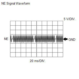
HINT:
- The correct waveform is as shown.
- NE stands for the crankshaft position sensor signal.
- Grounding failure of the shielded wire may cause a noisy waveform.
ECM Terminal Name
Between NE+ and NE-
Tester Range
5 V/DIV., 20 ms./DIV.
Condition
Idling with warm engine
MONITOR DESCRIPTION
If there is no signal from the crankshaft position sensor despite the crankshaft rotating, the ECM interprets this as a malfunction of the sensor.
MONITOR STRATEGY
| Related DTCs | P0335: Crankshaft position sensor verify pulse input P0335: Crankshaft position sensor range check/rationality |
| Required Sensors/Components (Main) | Crankshaft position sensor |
| Required Sensors/Components (Related) | Camshaft position sensor |
| Frequency of Operation | Continuous |
| Duration | -: Verify pulse input (case 1) 0.164 seconds: Range check/rationality 1.85 seconds: Verify pulse input (case 2) |
| MIL Operation | Immediate |
| Sequence of Operation | None |
TYPICAL ENABLING CONDITIONS
All| Monitor runs whenever the following DTCs are not stored | None |
| Both of the following conditions are met | - |
| Lost communication with hybrid vehicle control ECU (U0293) | Not detected |
| Hybrid control module judge | Engine running |
| All of the following conditions are met | - |
| Crankshaft position sensor | Signal input |
| Power switch | On (IG) |
| Time after starter off to on | 2.5 seconds or more |
| Camshaft position sensor circuit fail | Not detected |
| Number of camshaft position sensor signal pulse | 6 times |
| Auxiliary battery voltage | 7 V or higher |
| All of the following conditions are met | - |
| Engine speed | 600 rpm or higher |
| Starter | Off |
| Time after starter on to off | 3 seconds or more |
| Both of the following conditions are met | - |
| Power switch | On (IG) |
| Time after power switch off to on (IG) | 0.5 seconds or more |
TYPICAL MALFUNCTION THRESHOLDS
Range Check/Rationality| Number of crankshaft position sensor signal pulse | 87 times or less, or 219 times or more |
| Crankshaft position sensor signal | No signal |
COMPONENT OPERATING RANGE
| Crankshaft position sensor | |
CONFIRMATION DRIVING PATTERN
- Connect the Techstream to the DLC3.
- Turn the power switch on (IG) and turn the Techstream on.
- Clear the DTCs (even if no DTCs are stored, perform the clear DTC procedure).
- Turn the power switch off and wait for at least 30 seconds.
- Turn the power switch on (IG) and turn the Techstream on.
-
Put the engine in inspection mode (maintenance mode).
Click here
.gif)
- Start the engine.
- Idle the engine for 20 seconds or more [A].
- Enter the following menus: Powertrain / Engine and ECT / Trouble Codes [B].
-
Read the pending DTCs.
HINT:
- If a pending DTC is output, the system is malfunctioning.
- If a pending DTC is not output, perform the following procedure.
- Enter the following menus: Powertrain / Engine and ECT / Utility / All Readiness.
- Input the DTC: P0335.
-
Check the DTC judgment result.
Techstream Display
Description
NORMAL
- DTC judgment completed
- System normal
ABNORMAL
- DTC judgment completed
- System abnormal
INCOMPLETE
- DTC judgment not completed
- Perform driving pattern after confirming DTC enabling conditions
N/A
- Unable to perform DTC judgment
- Number of DTCs which do not fulfill DTC preconditions has reached ECU memory limit
HINT:
- If the judgment result shows NORMAL, the system is normal.
- If the judgment result shows ABNORMAL, the system has a malfunction.
- If the judgment result shows INCOMPLETE or N/A, perform steps [A] and [B] again.
-
If no pending DTC is output, perform a universal trip and check for permanent DTCs.
Click here
HINT:
- If a permanent DTC is output, the system is malfunctioning.
- If no permanent DTC is output, the system is normal.
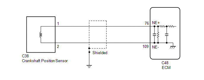
WIRING DIAGRAM
CAUTION / NOTICE / HINT
HINT:
-
After performing the inspection procedure for the crankshaft position sensor, if DTC P0335 is output again, check the following items related to the camshaft position sensor.
- Installation condition of the camshaft position sensor.
- Installation condition of the camshaft.
- Connection of the camshaft position sensor connector.
- If no problem is found through this diagnostic troubleshooting procedure, troubleshoot the engine mechanical system.
-
The engine speed can be checked by using the Techstream. To perform the check, follow the procedures below:
- Connect the Techstream to the DLC3.
- Turn the power switch on (IG).
- Turn the Techstream on.
-
Put the engine in inspection mode (maintenance mode).
Click here
- Start the engine.
- Enter the following menus: Powertrain / Engine and ECT / Data List / Primary / Engine Speed.
- The engine speed may be indicated as zero despite the engine running normally. This is caused by a lack of NE signals from the crankshaft position sensor. Alternatively, the engine speed may be indicated as lower than the actual engine speed if the crankshaft position sensor output voltage is insufficient.
- Read freeze frame data using the Techstream. The ECM records vehicle and driving condition information as freeze frame data the moment a DTC is stored. When troubleshooting, freeze frame data can help determine if the vehicle was moving or stationary, if the engine was warmed up or not, if the air fuel ratio was lean or rich, and other data from the time the malfunction occurred.
PROCEDURE
| 1. | READ VALUE USING TECHSTREAM (ENGINE SPEED) |
(a) Connect the Techstream to the DLC3.
(b) Turn the power switch on (IG).
(c) Turn the Techstream on.
(d) Put the engine in inspection mode (maintenance mode).
Click here
| Tester Display |
|---|
| Inspection Mode |
(e) Enter the following menus: Powertrain / Engine and ECT / Data List / Primary / Engine Speed.
Powertrain > Engine and ECT > Data List| Tester Display |
|---|
| Engine Speed |
(f) Start the engine.
(g) Read the values displayed on the Techstream while the engine is running.
Standard:
Correct values are displayed.
HINT:
- To check the engine speed change, display the graph on the Techstream.
- If the engine does not start, check the engine speed while cranking.
- If the engine speed indicated on the Techstream remains zero (0), there may be an open or short in the crankshaft position sensor circuit.
| OK | .gif) | CHECK FOR INTERMITTENT PROBLEMS |
|
.gif)
| 2. | INSPECT CRANKSHAFT POSITION SENSOR |
(a) Inspect the crankshaft position sensor.
Click here
| NG | | REPLACE CRANKSHAFT POSITION SENSOR |
|
| 3. | CHECK HARNESS AND CONNECTOR (CRANKSHAFT POSITION SENSOR - ECM) |
(a) Disconnect the crankshaft position sensor connector.
(b) Disconnect the ECM connector.
(c) Measure the resistance according to the value(s) in the table below.
Standard Resistance:
| Tester Connection | Condition | Specified Condition |
|---|---|---|
| C38-1 - C48-76 (NE+) | Always | Below 1 Ω |
| C38-2 - C48-109 (NE-) | Always | Below 1 Ω |
| C38-1 or C48-76 (NE+) - Body ground | Always | 10 kΩ or higher |
| C38-2 or C48-109 (NE-) - Body ground | Always | 10 kΩ or higher |
| NG | | REPAIR OR REPLACE HARNESS OR CONNECTOR |
|
| 4. | CHECK SENSOR INSTALLATION (CRANKSHAFT POSITION SENSOR) |
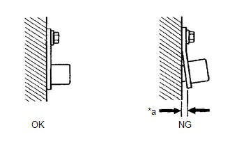
| *a | Clearance |
(a) Check the crankshaft position sensor installation condition.
OK:
Crankshaft position sensor is installed correctly.
| NG | | SECURELY REINSTALL CRANKSHAFT POSITION SENSOR |
|
| 5. | INSPECT CRANKSHAFT (TEETH OF CRANK ANGLE SENSOR PLATE) |
(a) Inspect the teeth of the crank angle sensor plate.
OK:
Crank angle sensor plate does not have any cracks or deformation.
| OK | | REPLACE ECM |
| NG | | REPLACE CRANKSHAFT |
READ NEXT:
 Camshaft Position Sensor Circuit (P0340,P0342,P0343)
DESCRIPTION The camshaft position sensor (VV1 signal) consists of a magnet and MRE (Magneto-Resistive Element). The camshaft has a timing rotor for the camshaft position sensor. When the camshaft rota
Ignition Coil "A" Primary / Secondary Circuit (P0351-P0354)
DESCRIPTION HINT:
These DTCs indicate malfunctions relating to the primary circuit.
If DTC P0351 is output, check the No. 1 ignition coil assembly (No. 1 cylinder) circuit.
If DTC P0352 is outp
Exhaust Gas Recirculation Flow Insufficient Detected (P0401)
DESCRIPTION Based on the driving conditions, the ECM regulates the volume of exhaust gas that is recirculated to the engine's combustion chambers and thus lowers the combustion temperature to reduce N
SEE MORE:
Vehicle Control History
VEHICLE CONTROL HISTORY NOTICE: When checking the vehicle control history, first record the output codes and after clearing the history, check the output history again. CHECK VEHICLE CONTROL HISTORY (LANE TRACING ASSIST SYSTEM) (a) Connect the Techstream to the DLC3. (b) Turn the power switch on (IG
Components
COMPONENTS ILLUSTRATION *1 CLEARANCE LIGHT ASSEMBLY LH *2 FRONT BUMPER ASSEMBLY *3 FRONT TURN SIGNAL LIGHT BULB - -
© 2016-2026 Copyright www.lexunx.com
